RDK-251 Power Integrations, RDK-251 Datasheet
RDK-251
Specifications of RDK-251
Available stocks


Related parts for RDK-251


RDK-251 Summary of contents
Page 1
... Meets IEC ringwave and EN55015 conducted EMI PF >0.9 at 115 VAC / 230 VAC %ATHD <10% at 115 VAC and <15% at 230 VAC Meets EN61000-3-2 harmonics contents 5245 Hellyer Avenue, San Jose, CA 95138 USA. Tel: +1 408 414 9200 Fax: +1 408 414 9201 TM Power Integrations www.powerint.com -PL LNK457DG ...
Page 2
... The products and applications illustrated herein (including transformer construction and circuits external to the products) may be covered by one or more U.S. and foreign patents, or potentially by pending U.S. and foreign patent applications assigned to Power Integrations. A complete list of Power Integrations' patents may be found at www.powerint.com. Power Integrations grants its customers a license under certain patent rights as set forth at < ...
Page 3
... Normal Steady State Operation..................................................................38 11.1.2 AC Start-up.................................................................................................40 11.1.3 115 V TRIAC in Series with AC Input .........................................................40 11.1.4 230 V TRIAC in Series with AC Input .........................................................42 11.1.5 Fault Conditions (Output Shorted / Open Circuit) .......................................43 11.2 Output Current Start-up Profile ..........................................................................44 Page Power Integrations Tel: +1 408 414 9200 Fax: +1 408 414 9201 www.powerint.com ...
Page 4
... This board is designed for non-isolated application and the engineering prototype has not been agency approved. Therefore, all testing should be performed using an isolation transformer to provide the AC input to the prototype board. Power Integrations, Inc. Tel: +1 408 414 9200 Fax: +1 408 414 9201 www.powerint.com ...
Page 5
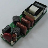
... LED load from the user. The document contains the power supply specification, schematic, bill of materials, transformer documentation, printed circuit layout, and performance data. Figure 1 – Populated Circuit Board Photograph (Top). Page Power Integrations Tel: +1 408 414 9200 Fax: +1 408 414 9201 www.powerint.com ...
Page 6
... Figure 2 – Populated Circuit Board Photograph (Bottom). Figure 3 – Example of RD-251 Used in an A19 LED Replacement Lamp (board removed from housing). Power Integrations, Inc. Tel: +1 408 414 9200 Fax: +1 408 414 9201 www.powerint.com Page ...
Page 7
... Mounted into A19 metal finned enclosure and measured on ground plane (to simulate end application) 1.2/50 s surge, IEC 1000-4-5, Series Impedance: Differential Mode: 2 200 A short-circuit Series Impedance: Differential Mode 0.83” (20.86 mm) x 2.52” (63.9 mm) Free convection, sea level Power Integrations www.powerint.com ...
Page 8
... R7 and R8 to 20 220 nF, R10 and R11 to 510 / 0.5 W minimum 150nF and R16 to 1 k / 0.25 W. Figure 4 – Schematic (highlighted blocks may be removed for non-dimming applications.) Power Integrations, Inc. Tel: +1 408 414 9200 Fax: +1 408 414 9201 www.powerint.com ...
Page 9
... Limiting operation to low line only (85 VAC to 132 VAC) allows the values of R7 and reduced as the peak currents that occur when a leading edge dimmer TRIAC fires are significantly lower. Both changes reduce dissipation and improve efficiency. Page Power Integrations Tel: +1 408 414 9200 Fax: +1 408 414 9201 www.powerint.com ...
Page 10
... For non-dimming application, both the active damper and bleeder network may be removed. To achieve this, the following parts can be deleted C6 and C3. Replace 0 for the following locations: R7, R8, and R20. Power Integrations, Inc. Tel: +1 408 414 9200 Fax: +1 408 414 9201 www.powerint.com ...
Page 11
... The CC mode set-point is determined by the voltage drop that appears across R18 which is then fed to the FB pin of U1. Output overvoltage protection is provided by VR2 and R14 (the effect of R14 on the current sense signal in negligible and can be ignored). Page Power Integrations Tel: +1 408 414 9200 Fax: +1 408 414 9201 www.powerint.com . ...
Page 12
... PCB Layout Figure 5 – Top Printed Circuit Layout 0.83” (20.86 mm) x 2.52” (63.9 mm). Power Integrations, Inc. Tel: +1 408 414 9200 Fax: +1 408 414 9201 www.powerint.com Figure 6 – Bottom Printed Circuit Layout. Page ...
Page 13
... RL1632R-R820-F Susumu Co Ltd NFR0200004709JR500 Vishay/BC Components V275LA4P SNX-R1536 LNK457DG Power Integrations MAZS2000ML Panasonic-SSG 5002 5000 5001 Power Integrations Tel: +1 408 414 9200 Fax: +1 408 414 9201 www.powerint.com Panasonic Panasonic Panasonic Panasonic Panasonic Panasonic Panasonic Rubycon Diode Inc. Diodes Inc Diodes Inc ...
Page 14
... Z 0.7 Open Enclosure Frame PO VD LinkSwitch-PL DESIGN VARIABLES Device LNK457 VOR Turns Ratio TON FSW Duty Cycle VDRAIN IRMS IPK Power Integrations, Inc. Tel: +1 408 414 9200 Fax: +1 408 414 9201 www.powerint.com INFO OUTPUT UNIT 85 V 265 10.0 V 0.350 A 0.7 %/100 0 ...
Page 15
... Primary Inductance Tolerance of Primary Inductance Primary Winding Number of Turns Gapped Core Effective Inductance Maximum (BM < 3000 G) AC Flux Density for Core Loss Curves (0.5 X Peak to Peak) Target Peak Flux density. Recommended value of BP_TARGET < 3700 G. Peak Flux Density (BP < 3700 G ) Power Integrations www.powerint.com ...
Page 16
... INPUT LG BWE OD INS DIA AWG CM CMA Primary Current Density (J) SECONDARY DESIGN PARAMETERS ISP ISRMS IO PIVS CMS1 AWGS DIAS ODS Power Integrations, Inc. Tel: +1 408 414 9200 Fax: +1 408 414 9201 www.powerint.com INFO OUTPUT UNIT 0.618 mm 25.8 mm 0.20 mm 0. AWG 32 Cmils ...
Page 17
... Varnish. [6] Page WD1: 1 half Secondary 10T – #28AWG WD3: 2 10T – #28AWG 6 Figure 7 – Transformer Electrical Diagram. Description Tel: +1 408 414 9200 Fax: +1 408 414 9201 half Seconadry 500 VAC 660 H, 1200 kHz (Min.) 15 H (Max.) Power Integrations www.powerint.com 10 % ...
Page 18
... Transformer Build Diagram Power Integrations, Inc. Tel: +1 408 414 9200 Fax: +1 408 414 9201 www.powerint.com 6 WD3 WD2 7 WD1 Figure 8 – Transformer Build Diagram. Figure 9 – Transformer Assembly. 10T – #28AWG 130T - #35AWG (wound in 3 layers: 44T+43T+43T) 10T – #28AWG Page ...
Page 19
... Start at pin 3, wind 10 bifilar turns of wire item [3] from left to right, and terminate Half of pin 6. Secondary 2 layers of tape item [5]. Insulation Grind core halves to get 660 H assemble with tape. Finish Varnish. Page Power Integrations Tel: +1 408 414 9200 Fax: +1 408 414 9201 www.powerint.com ...
Page 20
... WD1 st 1 Half of Secondary Insulation WD2 Primary Power Integrations, Inc. Tel: +1 408 414 9200 Fax: +1 408 414 9201 www.powerint.com Place bobbin on the mandrel such that primary on the left and secondary on the right. Winding direction is clock-wise direction. Start at pin 7, wind 10 bifilar turns of wire item [3] from right to left, and terminate at pin 3 ...
Page 21
... WD2 Primary (Cont’d) Insulation Page Refer to fig.7 above, and terminate at pin 1. 1 layer of tape item [5]. Power Integrations Tel: +1 408 414 9200 Fax: +1 408 414 9201 www.powerint.com ...
Page 22
... WD3 nd 2 Half of Secondary Insulation Finish Power Integrations, Inc. Tel: +1 408 414 9200 Fax: +1 408 414 9201 www.powerint.com Start at pin 3, wind 10 bifilar turns of wire item [3] from left to right, and terminate at pin 6. 2 layers of tape item [5]. Grind core halves to get 660H, between assemble with tape ...
Page 23
... Figure 11 – Full Load (15 V, 350 mA) Efficiency with Respect to Line Input Voltage and Dimming or Non- Dimming Configuration (active damper and bleeder removed). Page 140 160 180 200 Input Voltage (VAC) Tel: +1 408 414 9200 Fax: +1 408 414 9201 Non-Dimmable Dimmable 220 240 260 280 Power Integrations www.powerint.com ...
Page 24
... Table 1 – Full Load Characteristic, Verified with 5 White LED Series String. Power Integrations, Inc. Tel: +1 408 414 9200 Fax: +1 408 414 9201 www.powerint.com (W) PF %THD (V 6.728 0.9973 6.6400 15.12 6.981 0.9950 8 ...
Page 25
... Table 2 – Harmonics Contents Tel: +1 408 414 9200 Fax: +1 408 414 9201 EN 61000-3-2 230 V 32.52 1.51 P 1.57 P 1.72 P 1.64 P 1.63 P 1.55 P 1.31 P 1.05 P 0.73 P 0.99 P 0.53 P 0.66 P 0.50 P 0.45 P 0.36 P 0.30 P 0.39 P 0.35 P 0.36 P 0.28 0.24 0.27 0.18 0.15 Power Integrations www.powerint.com ...
Page 26
... Figure 12 – UUT Harmonic content. Power Integrations, Inc. Tel: +1 408 414 9200 Fax: +1 408 414 9201 www.powerint.com Harmonic Order 115 V Limit 115 V Non-Dimmable 115 V Dimmable 230 V Limit 230 V Non-Dimmable 230 V Dimmable Page ...
Page 27
... Figure 13 – Power Factor with Respect to AC Input at Full Load. Page 140 160 180 200 Input Voltage (VAC) Tel: +1 408 414 9200 Fax: +1 408 414 9201 Non-dimmable Dimmable 220 240 260 280 Power Integrations www.powerint.com ...
Page 28
... Figure 14 – Line Regulation, Room Temperature, Full Load. Power Integrations, Inc. Tel: +1 408 414 9200 Fax: +1 408 414 9201 www.powerint.com 140 160 180 200 Line Input Voltage (VAC) Dimmable Non-Dimmable 220 240 260 280 ...
Page 29
... TRIAC dimmer. Data was taken in 1 degree phase angle steps. 180 160 140 Dimming Angle (Degrees) Figure 15 – 115 V Phase Angle Dimming Characteristic (Increasing Output Current). Page 120 100 80 60 Tel: +1 408 414 9200 Fax: +1 408 414 9201 0.40 0.35 0.30 0.25 0.20 0.15 0.10 0.05 0. Power Integrations www.powerint.com ...
Page 30
... Figure 16 – 115 V Phase Angle Dimming Characteristic (Decreasing Output Current). Power Integrations, Inc. Tel: +1 408 414 9200 Fax: +1 408 414 9201 www.powerint.com 60 80 100 120 Dimming Angle (Degrees) 140 160 180 Page ...
Page 31
... Dimming Angle (Degrees) Figure 17 – 230 V Phase Angle Dimming Characteristic (Increasing Output Current). Page 120 100 80 60 Tel: +1 408 414 9200 Fax: +1 408 414 9201 0.40 0.35 0.30 0.25 0.20 0.15 0.10 0.05 0. Power Integrations www.powerint.com ...
Page 32
... Figure 18 – 230 V Phase Angle Dimming Characteristic (Increasing Output Current). Power Integrations, Inc. Tel: +1 408 414 9200 Fax: +1 408 414 9201 www.powerint.com 60 80 100 120 Dimming Angle (Degrees) 140 160 180 Page ...
Page 33
... Figure 19 – Sample Curve for Unit to Unit Output Current Dimming Performance at 115 Hz. Page 100 120 Dimming Angle (Degrees) Tel: +1 408 414 9200 Fax: +1 408 414 9201 Unit 1 Unit 2 140 160 180 Power Integrations www.powerint.com ...
Page 34
... Figure 20 – Sample Curve for Unit to Unit Output Current Dimming Performance at 230 Hz. Power Integrations, Inc. Tel: +1 408 414 9200 Fax: +1 408 414 9201 www.powerint.com 60 80 100 120 Dimming Angle (Degrees) Unit 2 Unit 2 140 160 ...
Page 35
... The unit was verified inside a cardboard box to avoid the influence of circulating air inside the thermal chamber. Figure 21 – Thermal Chamber Set-up Showing Box Used to Prevent Airflow Over UUT. Page Figure 22 – UUT Within Box. Tel: +1 408 414 9200 Fax: +1 408 414 9201 Power Integrations www.powerint.com ...
Page 36
... LED replacement enclosure. Supply correctly started up and operated at -30°C Item Ambient (ºC) Bridge (BR1) Fet (damper) (Q2) Input Inductor (L2) Transformer Core (T1) Transformer Winding (T1) LNK457 (U1) Output Capacitor (C11) Output Diode (D5) Power Integrations, Inc. Tel: +1 408 414 9200 Fax: +1 408 414 9201 www.powerint.com Normal Operation (º 115 V 230 ...
Page 37
... Thermal Scan Figure 23 – LNK457DG Device Temperature at 25ºC Open Air. Figure 24 – Bottom Side of PCB, Trace and Device Temperature. Page Load: 5 LED in series ( 350 mA) Tel: +1 408 414 9200 Fax: +1 408 414 9201 Power Integrations www.powerint.com ...
Page 38
... Figure 27 – 115 VAC / 60 Hz, 6 LED in Series (18 350 mA). Upper 100 V / div div. DRAIN Lower 0 div. DRAIN Power Integrations, Inc. Tel: +1 408 414 9200 Fax: +1 408 414 9201 www.powerint.com Figure 26 – 90 VAC / 50 Hz, 6 LED in Series (18 350 mA). , 100 V / div., 1 s / div. Upper: V DRAIN Lower ...
Page 39
... Figure 30 – 230 VAC / 50 Hz, 6 LED in Series (18 350 mA). , 200 V / div., 5 s / div. Upper: V DRAIN Lower 0 div. DRAIN Figure 32 – 265 VAC / 63 Hz, 6 LED in Series (18 350 mA). , 200 V / div., 5 s / div. Upper: V DRAIN Lower 0 div. DRAIN Power Integrations Tel: +1 408 414 9200 Fax: +1 408 414 9201 www.powerint.com ...
Page 40
... Dimming Phase Angle. 6 LED in Series (18 350 mA). Ch1(Yellow 100 V / div. DS Ch2(Red div. IN Ch4(Green 200 mA / div div. DS Power Integrations, Inc. Tel: +1 408 414 9200 Fax: +1 408 414 9201 www.powerint.com Figure 34 – 265 VAC / 63 Hz, 6 LED in Series (18 350 mA). Ch1(Yellow Ch2(Red div. O Ch3(Blue 100 mA / div. ...
Page 41
... Ch2(Red div. IN Ch4(Green 200 mA / div., 50 µs / div. DS Figure 40 – 115 VAC / 60 Hz, 135º Dimming Phase Angle. 6 LED in Series (18 350 mA) Ch1(Yellow 100 V / div. DS Ch2(Red div. IN Ch4(Green 200 mA / div., 50 µs / div. DS Power Integrations Tel: +1 408 414 9200 Fax: +1 408 414 9201 www.powerint.com ...
Page 42
... LED in Series (18 350 mA) Ch1(Yellow 200 V / div. DS Ch2(Red 200 V / div. IN Ch4(Green 200 mA / div div. DS Power Integrations, Inc. Tel: +1 408 414 9200 Fax: +1 408 414 9201 www.powerint.com Figure 42 – 230 VAC / 50 Hz, 45º Dimming Phase Angle. 6 LED in Series (18 350 mA) Ch1(Yellow 200 V / div. DS Ch2(Red 200 V / div ...
Page 43
... Dimming Phase Angle. 6 LED in Series (18 350 mA) Ch1(Yellow): V Ch2(Red): V Ch4(Green): I Figure 48 – 265 VAC. Load Shorted. Upper: V Lower: I Tel: +1 408 414 9200 Fax: +1 408 414 9201 , 200 V / div 200 V / div 200 mA / div., 20 µs / div 200 V / div. DRAIN , 0 div., 1 µs / div. DRAIN Power Integrations www.powerint.com ...
Page 44
... LED in Series (15V). Ch1(Yellow 100 V / div. IN Ch2(Red div. O Ch3(Blue 100 mA / div. O Ch4(Green 500 mA / div div. IN Power Integrations, Inc. Tel: +1 408 414 9200 Fax: +1 408 414 9201 www.powerint.com Figure 50 – 265 VAC. Load Open. Ch1(Yellow 200 V / div. DS Ch2(Red div. O Ch4(Green 200 mA / div., 20 µs / div. ...
Page 45
... Figure 56 – 115 VAC / 60 Hz. Tel: +1 408 414 9200 Fax: +1 408 414 9201 5 LED in Series (15 V). Ch1(Yellow 100 V / div. IN Ch2(Red div. O Ch3(Blue 100 mA / div. O Ch4(Green 500 mA / div div LED in Series (15 V). Ch1(Yellow div. IN Ch2(Red div. O Ch3(Blue 100 mA / div. O Ch4(Green div div. IN Power Integrations www.powerint.com ...
Page 46
... Dimming Phase Angle. 5 LED in Series (15 V). Ch1(Yellow div. IN Ch2(Red div. O Ch3(Blue 100 mA / div. O Ch4(Green div div. IN Power Integrations, Inc. Tel: +1 408 414 9200 Fax: +1 408 414 9201 www.powerint.com Figure 58 – 265 VAC / 63 Hz and Figure 60 – 230 VAC / 50 Hz. 5 LED in Series (15 V). ...
Page 47
... Figure 64 – 230 VAC / 50 Hz. 45º Dimming Phase Angle. 5 LED in Series (15 V) Ch1(Yellow): V Ch2(Red): V Ch3(Blue): I Ch4(Green): I Tel: +1 408 414 9200 Fax: +1 408 414 9201 , 100 V / div div 100 mA / div div div 100 V / div div 100 mA / div div div. IN Power Integrations www.powerint.com ...
Page 48
... Ch1(Yellow 100 V / div. DS Ch2(Red 200 V / div. IN Ch3(Blue 100 mA / div. O Ch4(Green 200 mA / div div. DS Power Integrations, Inc. Tel: +1 408 414 9200 Fax: +1 408 414 9201 www.powerint.com Figure 66 – 115-85-115 VAC / 60 Hz. 5 LED in Series (15 V). Ch1(Yellow 100 V / div. DS Ch2(Red 200 V / div. IN Ch3(Blue 100 mA / div. ...
Page 49
... Figure 70 – 115-132-115 VAC / 60 Hz. 5 LED in Series (15 V). Ch1(Yellow): V Ch2(Red): V Ch3(Blue): I Ch4(Green): I Tel: +1 408 414 9200 Fax: +1 408 414 9201 , 100 V / div 200 V / div 100 mA / div 200 mA / div div DS , 100 V / div 200 V / div 100 mA / div 200 mA / div div. DS Power Integrations www.powerint.com ...
Page 50
... Ch1(Yellow 200 V / div. DS Ch2(Red 200 V / div. IN Ch3(Blue 100 mA / div. O Ch4(Green 200 mA / div div. DS Power Integrations, Inc. Tel: +1 408 414 9200 Fax: +1 408 414 9201 www.powerint.com Figure 72 – 115-132-115 VAC / 60 Hz. 5 LED in Series (15 V). Ch1(Yellow 100 V / div. DS Ch2(Red 200 V / div. IN Ch3(Blue 100 mA / div. ...
Page 51
... Figure 78 – 230-265-230 VAC / 50 Hz. 5 LED in Series (15 V). Ch1(Yellow): V Ch2(Red): V Ch3(Blue): I Ch4(Green): I Tel: +1 408 414 9200 Fax: +1 408 414 9201 , 200 V / div 200 V / div 100 mA / div 200 mA / div., 50ms / div 200 V / div 200 V / div 100 mA / div 200 mA / div div. DS Power Integrations www.powerint.com ...
Page 52
... V / 350 mA) and operation was verified following each surge event. Input Surge Level Voltage (V) (VAC) +500 230 -500 230 +2500 230 -2500 230 Unit passed all test conditions. Power Integrations, Inc. Tel: +1 408 414 9200 Fax: +1 408 414 9201 www.powerint.com Injection Injection Phase Location (° Ring Wave (200 A) ...
Page 53
... EMI Test Set-up LED driver is placed in a conical metal housing (for self-ballasted lamps; CISPR15 Edition 7.2). Figure 79 – Conducted Emissions Measurement Set-up Showing Conical Ground Plane Inside which UUT was Mounted. Page Power Integrations Tel: +1 408 414 9200 Fax: +1 408 414 9201 www.powerint.com ...
Page 54
... Figure 80– Pre-scan Conducted EMI, Maximum Steady State Load, 115 VAC, 60 Hz, and EN55015 Limits. Note Blue Line is Peak Result vs. QP Limit Line – Refer to Table for QP Margin. Table 4 – Conducted EMI, Maximum Steady State Load, 115 VAC, 60 Hz, and EN55015 Margin. Power Integrations, Inc. Tel: +1 408 414 9200 Fax: +1 408 414 9201 www.powerint.com ...
Page 55
... Table 5 – Conducted EMI, Maximum Steady State Load, 230 VAC, 60 Hz, and EN55015 Margin. Page RBW 9 kHz MT 500 ms Att 10 dB AUTO 100 kHz 1 MHz LIMIT CHECK PASS EN55015A Tel: +1 408 414 9200 Fax: +1 408 414 9201 10 MHz SGL TDF 6DB 30 MHz Power Integrations www.powerint.com ...
Page 56
... Hz 100 W 500 W 230 Note: **** Holding current of dimmer is well above the drawn current of UUT ** 6 units in parallel * 3 units in parallel N.S. – Not Specified. Power Integrations, Inc. Tel: +1 408 414 9200 Fax: +1 408 414 9201 www.powerint.com Part Dimmer r Number Type DIING CHUNG WS-5005 ...
Page 57
... Load: Iout in mA 348 351 354 357 360 363 366 369 115V, 60Hz, 16V Load: Iout . C PK Tel: +1 408 414 9200 Fax: +1 408 414 9201 Mean 362.0 StDev 5.608 N 267 Mean 356.5 StDev 4.122 N 267 372 provides process capability P Power Integrations www.powerint.com ...
Page 58
... Table 6 - Output current tolerance vs C The data in Table 6 shows that the design meets the +/-7% target specification with >1.33. In additional the design is capable of meeting a tolerance specification of < +/- 5% at low line. Power Integrations, Inc. Tel: +1 408 414 9200 Fax: +1 408 414 9201 www.powerint.com =C ...
Page 59
... Description & changes 1.8 Initial Release 1.9 BOM Updated 1.91 Production distribution of output current added (section 15). 1.92 Edited distribution test Tel: +1 408 414 9200 Fax: +1 408 414 9201 Reviewed Apps & Mktg Apps & Mktg Apps & Mktg Power Integrations www.powerint.com ...
Page 60
... For the latest updates, visit our website: www.powerint.com Power Integrations reserves the right to make changes to its products at any time to improve reliability or manufacturability. Power Integrations does not assume any liability arising from the use of any device or circuit described herein. POWER INTEGRATIONS MAKES NO WARRANTY HEREIN AND SPECIFICALLY DISCLAIMS ALL WARRANTIES INCLUDING, WITHOUT LIMITATION, THE IMPLIED WARRANTIES OF MERCHANTABILITY, FITNESS FOR A PARTICULAR PURPOSE, AND NON-INFRINGEMENT OF THIRD PARTY RIGHTS ...