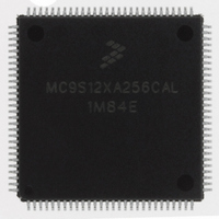
MC9S12XA256CAL Freescale Semiconductor, MC9S12XA256CAL Datasheet - Page 413

MC9S12XA256CAL
Manufacturer Part Number
MC9S12XA256CAL
Description
IC MCU 256K FLASH 112-LQFP
Manufacturer
Freescale Semiconductor
Series
HCS12r
Specifications of MC9S12XA256CAL
Core Processor
HCS12X
Core Size
16-Bit
Speed
80MHz
Connectivity
EBI/EMI, I²C, IrDA, LIN, SCI, SPI
Peripherals
LVD, POR, PWM, WDT
Number Of I /o
91
Program Memory Size
256KB (256K x 8)
Program Memory Type
FLASH
Eeprom Size
4K x 8
Ram Size
16K x 8
Voltage - Supply (vcc/vdd)
2.35 V ~ 5.5 V
Data Converters
A/D 16x10b
Oscillator Type
External
Operating Temperature
-40°C ~ 85°C
Package / Case
112-LQFP
No. Of I/o's
91
Eeprom Memory Size
4KB
Ram Memory Size
16KB
Cpu Speed
80MHz
No. Of Timers
1
No. Of Pwm Channels
8
Digital Ic Case Style
LQFP
Rohs Compliant
Yes
Processor Series
S12XA
Core
HCS12
Data Bus Width
16 bit
Data Ram Size
16 KB
Interface Type
CAN, I2C, SCI, SPI
Maximum Clock Frequency
40 MHz
Number Of Programmable I/os
91
Number Of Timers
12
Maximum Operating Temperature
+ 85 C
Mounting Style
SMD/SMT
3rd Party Development Tools
EWHCS12
Development Tools By Supplier
EVB9S12XDP512E
Minimum Operating Temperature
- 40 C
On-chip Adc
2 (10 bit, 16 Channel)
Package
112LQFP
Family Name
HCS12
Maximum Speed
40 MHz
Operating Supply Voltage
2.5|5 V
Lead Free Status / RoHS Status
Lead free / RoHS Compliant
Available stocks
Company
Part Number
Manufacturer
Quantity
Price
Company:
Part Number:
MC9S12XA256CAL
Manufacturer:
AD
Quantity:
101
Company:
Part Number:
MC9S12XA256CAL
Manufacturer:
Freescale Semiconductor
Quantity:
10 000
Part Number:
MC9S12XA256CAL
Manufacturer:
FREESCALE
Quantity:
20 000
- Current page: 413 of 1348
- Download datasheet (8Mb)
9.5
The reset state of each individual bit is listed in
details the registers and their bit-fields.
9.6
IICV2 uses only one interrupt vector.
Internally there are three types of interrupts in IIC. The interrupt service routine can determine the interrupt
type by reading the status register.
IIC Interrupt can be generated on
The IIC interrupt is enabled by the IBIE bit in the IIC control register. It must be cleared by writing 0 to
the IBF bit in the interrupt service routine.
9.7
9.7.1
9.7.1.1
Reset will put the IIC bus control register to its default status. Before the interface can be used to transfer
serial data, an initialization procedure must be carried out, as follows:
Freescale Semiconductor
1. Arbitration lost condition (IBAL bit set)
2. Byte transfer condition (TCF bit set)
3. Address detect condition (IAAS bit set)
1. Update the frequency divider register (IBFD) and select the required division ratio to obtain SCL
2. Update the IIC bus address register (IBAD) to define its slave address.
3. Set the IBEN bit of the IIC bus control register (IBCR) to enable the IIC interface system.
4. Modify the bits of the IIC bus control register (IBCR) to select master/slave mode, transmit/receive
frequency from system clock.
mode and interrupt enable or not.
Interrupt
Interrupt
Resets
Interrupts
Initialization/Application Information
IIC
IIC Programming Examples
Initialization Sequence
Offset
—
Vector
—
MC9S12XDP512 Data Sheet, Rev. 2.21
Priority
Table 9-8. Interrupt Summary
—
IBAL, TCF, IAAS
Section 9.3, “Memory Map and Register
bits in IBSR
Source
register
Chapter 9 Inter-Integrated Circuit (IICV2) Block Description
When either of IBAL, TCF or IAAS bits is set
may cause an interrupt based on arbitration
lost, transfer complete or address detect
conditions
Description
Definition,” which
413
Related parts for MC9S12XA256CAL
Image
Part Number
Description
Manufacturer
Datasheet
Request
R
Part Number:
Description:
Manufacturer:
Freescale Semiconductor, Inc
Datasheet:
Part Number:
Description:
Manufacturer:
Freescale Semiconductor, Inc
Datasheet:
Part Number:
Description:
Manufacturer:
Freescale Semiconductor, Inc
Datasheet:
Part Number:
Description:
Manufacturer:
Freescale Semiconductor, Inc
Datasheet:
Part Number:
Description:
Manufacturer:
Freescale Semiconductor, Inc
Datasheet:
Part Number:
Description:
Manufacturer:
Freescale Semiconductor, Inc
Datasheet:
Part Number:
Description:
Manufacturer:
Freescale Semiconductor, Inc
Datasheet:
Part Number:
Description:
Manufacturer:
Freescale Semiconductor, Inc
Datasheet:
Part Number:
Description:
Manufacturer:
Freescale Semiconductor, Inc
Datasheet:
Part Number:
Description:
Manufacturer:
Freescale Semiconductor, Inc
Datasheet:
Part Number:
Description:
Manufacturer:
Freescale Semiconductor, Inc
Datasheet:
Part Number:
Description:
Manufacturer:
Freescale Semiconductor, Inc
Datasheet:
Part Number:
Description:
Manufacturer:
Freescale Semiconductor, Inc
Datasheet:
Part Number:
Description:
Manufacturer:
Freescale Semiconductor, Inc
Datasheet:
Part Number:
Description:
Manufacturer:
Freescale Semiconductor, Inc
Datasheet:


