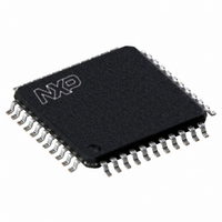
P89V662FBC,557 NXP Semiconductors, P89V662FBC,557 Datasheet - Page 69

P89V662FBC,557
Manufacturer Part Number
P89V662FBC,557
Description
IC 80C51 MCU FLASH 32K 44-TQFP
Manufacturer
NXP Semiconductors
Series
89Vr
Datasheet
1.P89V660FBC557.pdf
(89 pages)
Specifications of P89V662FBC,557
Program Memory Type
FLASH
Program Memory Size
32KB (32K x 8)
Package / Case
44-TQFP
Core Processor
8051
Core Size
8-Bit
Speed
40MHz
Connectivity
I²C, SPI, UART/USART
Peripherals
POR, PWM, WDT
Number Of I /o
36
Ram Size
1K x 8
Voltage - Supply (vcc/vdd)
4.5 V ~ 5.5 V
Oscillator Type
Internal
Operating Temperature
-40°C ~ 85°C
Processor Series
P89V6x
Core
80C51
Data Bus Width
8 bit
Data Ram Size
1 KB
Interface Type
I2C/UART
Maximum Clock Frequency
40 MHz
Number Of Programmable I/os
36
Number Of Timers
3
Operating Supply Voltage
4.5 V to 5.5 V
Maximum Operating Temperature
+ 85 C
Mounting Style
SMD/SMT
3rd Party Development Tools
PK51, CA51, A51, ULINK2
Minimum Operating Temperature
- 40 C
Lead Free Status / RoHS Status
Lead free / RoHS Compliant
For Use With
622-1001 - USB IN-CIRCUIT PROG 80C51ISP
Eeprom Size
-
Data Converters
-
Lead Free Status / Rohs Status
Lead free / RoHS Compliant
Other names
568-2435
935280832557
P89V662FBC
935280832557
P89V662FBC
Available stocks
Company
Part Number
Manufacturer
Quantity
Price
Company:
Part Number:
P89V662FBC,557
Manufacturer:
Maxim
Quantity:
260
Company:
Part Number:
P89V662FBC,557
Manufacturer:
NXP Semiconductors
Quantity:
10 000
NXP Semiconductors
Table 67.
P89V660_662_664_3
Product data sheet
Mode
Idle mode
Power-down
mode
Power-saving modes
6.13.1 Idle mode
6.13.2 Power-down mode
Initiated by
Software (Set IDL bit in
PCON) MOV PCON, #01H
Software (Set PD bit in
PCON) MOV PCON, #02H
Idle mode is entered setting the IDL bit in the PCON register. In Idle mode, the program
counter is stopped. The system clock continues to run and all interrupts and peripherals
remain active. The on-chip RAM and the special function registers hold their data during
this mode.
The device exits Idle mode through either a system interrupt or a hardware reset. Exiting
Idle mode via system interrupt, the start of the interrupt clears the IDL bit and exits Idle
mode. After exit the Interrupt Service Routine, the interrupted program resumes execution
beginning at the instruction immediately following the instruction which invoked the Idle
mode. A hardware reset starts the device similar to a power-on reset.
The Power-down mode is entered by setting the PD bit in the PCON register. In the
Power-down mode, the clock is stopped and external interrupts are active for level
sensitive interrupts only. SRAM contents are retained during Power-down, the minimum
V
The device exits Power-down mode through either an enabled external level sensitive
interrupt or a hardware reset. The start of the interrupt clears the PD bit and exits
Power-down. Holding the external interrupt pin low restarts the oscillator, the signal must
hold low at least 1024 clock cycles before bringing back high to complete the exit. Upon
interrupt signal restored to logic V
resumes beginning at the instruction immediately following the instruction which invoked
Power-down mode. A hardware reset starts the device similar to power-on reset.
To exit properly out of Power-down, the reset or external interrupt should not be executed
before the V
long enough at its normal operating level for the oscillator to restart and stabilize (normally
less than 10 ms).
DD
level is 2.0 V.
DD
line is restored to its normal operating voltage. Be sure to hold V
State of MCU
CLK is running. Interrupts,
serial port and timers/counters
are active. Program Counter is
stopped. ALE and PSEN
signals at a HIGH-state during
Idle. All registers remain
unchanged.
CLK is stopped. On-chip SRAM
and SFR data is maintained.
ALE and PSEN signals at a
LOW-state during power-down.
External Interrupts are only
active for level sensitive
interrupts, if enabled.
Rev. 03 — 10 November 2008
IH
80C51 with 512 B/1 kB/2 kB RAM, dual I
, the interrupt service routine program execution
Exited by
Enabled interrupt or hardware reset. Start of
interrupt clears IDL bit and exits Idle mode,
after the ISR RETI instruction, program
resumes execution beginning at the
instruction following the one that invoked
Idle mode. A hardware reset restarts the
device similar to a power-on reset.
Enabled external level sensitive interrupt or
hardware reset. Start of interrupt clears PD
bit and exits Power-down mode, after the
ISR RETI instruction program resumes
execution beginning at the instruction
following the one that invoked Power-down
mode. A hardware reset restarts the device
similar to a power-on reset.
P89V660/662/664
© NXP B.V. 2008. All rights reserved.
2
C-bus, SPI
DD
voltage
69 of 89


