ATTINY9-MAHR Atmel, ATTINY9-MAHR Datasheet - Page 79
ATTINY9-MAHR
Manufacturer Part Number
ATTINY9-MAHR
Description
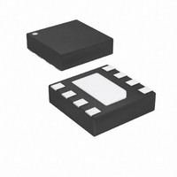
IC MCU AVR 1K FLASH 8UDFN
Manufacturer
Atmel
Series
AVR® ATtinyr
Datasheet
1.ATTINY9-MAHR.pdf
(169 pages)
Specifications of ATTINY9-MAHR
Package / Case
8-UDFN Exposed Pad
Voltage - Supply (vcc/vdd)
1.8 V ~ 5.5 V
Operating Temperature
-40°C ~ 85°C
Speed
12MHz
Number Of I /o
4
Core Processor
AVR
Program Memory Type
FLASH
Ram Size
32 x 8
Program Memory Size
1KB (1K x 8)
Oscillator Type
Internal
Peripherals
POR, PWM, WDT
Core Size
8-Bit
Lead Free Status / RoHS Status
Lead free / RoHS Compliant
Eeprom Size
-
Data Converters
-
Connectivity
-
Lead Free Status / Rohs Status
Details
Available stocks
Company
Part Number
Manufacturer
Quantity
Price
Company:

Part Number:
ATTINY9-MAHR
Manufacturer:
ST
Quantity:
101


11.11.7
11.11.8
8127D–AVR–02/10
ICR0H and ICR0L – Input Capture Register 0
TIMSK0 – Timer/Counter Interrupt Mask Register 0
8-bit temporary high byte register (TEMP). This temporary register is shared by all the other 16-
bit registers. See
The Input Capture is updated with the counter (TCNT0) value each time an event occurs on the
ICP0 pin (or optionally on the Analog Comparator output for Timer/Counter0). The Input Capture
can be used for defining the counter TOP value.
The Input Capture Register is 16-bit in size. To ensure that both the high and low bytes are read
simultaneously when the CPU accesses these registers, the access is performed using an 8-bit
temporary high byte register (TEMP). This temporary register is shared by all the other 16-bit
registers.
• Bits 7:6, 4:3 – Reserved Bits
These bits are reserved for future use. For ensuring compatibility with future devices, these bits
must be written to zero when the register is written.
• Bit 5 – ICIE0: Timer/Counter0, Input Capture Interrupt Enable
When this bit is written to one, and the I-flag in the Status Register is set (interrupts globally
enabled), the Timer/Counter0 Input Capture interrupt is enabled. The
corresponding Interrupt Vector (See “Interrupts” on page 66.) is executed when the
ICF0 Flag, located in TIFR0, is set.
• Bit 2 – OCIE0B: Timer/Counter0, Output Compare B Match Interrupt Enable
When this bit is written to one, and the I-flag in the Status Register is set (interrupts globally
enabled), the Timer/Counter0 Output Compare B Match interrupt is enabled. The corresponding
Interrupt Vector (see
TIFR0, is set.
• Bit 1 – OCIE0A: Timer/Counter0, Output Compare A Match Interrupt Enable
When this bit is written to one, and the I-flag in the Status Register is set (interrupts globally
enabled), the Timer/Counter0 Output Compare A Match interrupt is enabled. The corresponding
Interrupt Vector (see
TIFR0, is set.
• Bit 0 – TOIE0: Timer/Counter0, Overflow Interrupt Enable
When this bit is written to one, and the I-flag in the Status Register is set (interrupts globally
enabled), the Timer/Counter0 Overflow interrupt is enabled. The corresponding Interrupt Vector
(see
Bit
0x23
0x22
Read/Write
Initial Value
Bit
0x2B
Read/Write
Initial Value
“Interrupts” on page
“Accessing 16-bit Registers” on page
R/W
R
“Accessing 16-bit Registers” on page
7
0
7
–
0
“Interrupts” on page
“Interrupts” on page
R/W
36) is executed when the TOV0 flag, located in TIFR0, is set.
R
6
0
6
–
0
R/W
ICIE0
R/W
5
0
5
0
R/W
36) is executed when the OCF0B flag, located in
36) is executed when the OCF0A flag, located in
4
0
R
4
–
0
ICR0[15:8]
ICR0[7:0]
72.
R/W
3
0
R
3
–
0
72.
OCIE0B
R/W
R/W
2
0
2
0
ATtiny4/5/9/10
OCIE0A
R/W
R/W
1
0
1
0
R/W
TOIE0
R/W
0
0
0
0
ICR0H
TIMSK0
ICR0L
79
Related parts for ATTINY9-MAHR
Image
Part Number
Description
Manufacturer
Datasheet
Request
R

Part Number:
Description:
Manufacturer:
Atmel Corporation
Datasheet:

Part Number:
Description:
IC MCU AVR 1KB FLASH SOT-23-6
Manufacturer:
Atmel
Datasheet:
Part Number:
Description:
IC MCU AVR 1KB FLASH SOT-23-6
Manufacturer:
Atmel
Datasheet:

Part Number:
Description:
IC MCU AVR 1K FLASH 8UDFN
Manufacturer:
Atmel
Datasheet:

Part Number:
Description:
DEV KIT FOR AVR/AVR32
Manufacturer:
Atmel
Datasheet:
Part Number:
Description:
INTERVAL AND WIPE/WASH WIPER CONTROL IC WITH DELAY
Manufacturer:
ATMEL Corporation
Datasheet:
Part Number:
Description:
Low-Voltage Voice-Switched IC for Hands-Free Operation
Manufacturer:
ATMEL Corporation
Datasheet:
Part Number:
Description:
MONOLITHIC INTEGRATED FEATUREPHONE CIRCUIT
Manufacturer:
ATMEL Corporation
Datasheet:
Part Number:
Description:
AM-FM Receiver IC U4255BM-M
Manufacturer:
ATMEL Corporation
Datasheet:
Part Number:
Description:
Monolithic Integrated Feature Phone Circuit
Manufacturer:
ATMEL Corporation
Datasheet:
Part Number:
Description:
Multistandard Video-IF and Quasi Parallel Sound Processing
Manufacturer:
ATMEL Corporation
Datasheet:
Part Number:
Description:
High-performance EE PLD
Manufacturer:
ATMEL Corporation
Datasheet: