ATTINY9-MAHR Atmel, ATTINY9-MAHR Datasheet - Page 114
ATTINY9-MAHR
Manufacturer Part Number
ATTINY9-MAHR
Description
IC MCU AVR 1K FLASH 8UDFN
Manufacturer
Atmel
Series
AVR® ATtinyr
Datasheet
1.ATTINY9-MAHR.pdf
(169 pages)
Specifications of ATTINY9-MAHR
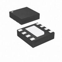
Package / Case
8-UDFN Exposed Pad
Voltage - Supply (vcc/vdd)
1.8 V ~ 5.5 V
Operating Temperature
-40°C ~ 85°C
Speed
12MHz
Number Of I /o
4
Core Processor
AVR
Program Memory Type
FLASH
Ram Size
32 x 8
Program Memory Size
1KB (1K x 8)
Oscillator Type
Internal
Peripherals
POR, PWM, WDT
Core Size
8-Bit
Lead Free Status / RoHS Status
Lead free / RoHS Compliant
Eeprom Size
-
Data Converters
-
Connectivity
-
Lead Free Status / Rohs Status
Details
Available stocks
Company
Part Number
Manufacturer
Quantity
Price
Company:

Part Number:
ATTINY9-MAHR
Manufacturer:
ST
Quantity:
101


15.4.3.2
15.4.3.3
15.4.3.4
15.4.3.5
114
ATtiny4/5/9/10
Erasing the Code Section
Writing a Code Word
Erasing the Configuration Section
Writing a Configuration Word
Before starting the Chip erase, the NVMCMD register must be loaded with the CHIP_ERASE
command. To start the erase operation a dummy byte must be written into the high byte of a
word location that resides inside the Flash code section. The NVMBSY bit remains set until eras-
ing has been completed. While the Flash is being erased neither Flash buffer loading nor Flash
reading can be performed.
The Chip Erase can be carried out as follows:
The algorithm for erasing all pages of the Flash code section is as follows:
The algorithm for writing a word to the code section is as follows:
The algorithm for erasing the Configuration section is as follows:
The algorithm for writing a Configuration word is as follows.
1. Write the CHIP_ERASE command to the NVMCMD register
2. Start the erase operation by writing a dummy byte to the high byte of any word location
3. Wait until the NVMBSY bit has been cleared
1. Write the SECTION_ERASE command to the NVMCMD register
2. Start the erase operation by writing a dummy byte to the high byte of any word location
3. Wait until the NVMBSY bit has been cleared
1. Write the WORD_WRITE command to the NVMCMD register
2. Write the low byte of the data into the low byte of a word location
3. Write the high byte of the data into the high byte of the same word location. This will
4. Wait until the NVMBSY bit has been cleared
1. Write the SECTION_ERASE command to the NVMCMD register
2. Start the erase operation by writing a dummy byte to the high byte of any word location
3. Wait until the NVMBSY bit has been cleared
1. Write the WORD_WRITE command to the NVMCMD register
2. Write the low byte of the data to the low byte of a configuration word location
3. Write the high byte of the data to the high byte of the same configuration word location.
4. Wait until the NVMBSY bit has been cleared
inside the code section
inside the code section
start the Flash write operation
inside the configuration section
This will start the Flash write operation.
8127D–AVR–02/10
Related parts for ATTINY9-MAHR
Image
Part Number
Description
Manufacturer
Datasheet
Request
R

Part Number:
Description:
Manufacturer:
Atmel Corporation
Datasheet:

Part Number:
Description:
IC MCU AVR 1KB FLASH SOT-23-6
Manufacturer:
Atmel
Datasheet:
Part Number:
Description:
IC MCU AVR 1KB FLASH SOT-23-6
Manufacturer:
Atmel
Datasheet:

Part Number:
Description:
IC MCU AVR 1K FLASH 8UDFN
Manufacturer:
Atmel
Datasheet:

Part Number:
Description:
DEV KIT FOR AVR/AVR32
Manufacturer:
Atmel
Datasheet:
Part Number:
Description:
INTERVAL AND WIPE/WASH WIPER CONTROL IC WITH DELAY
Manufacturer:
ATMEL Corporation
Datasheet:
Part Number:
Description:
Low-Voltage Voice-Switched IC for Hands-Free Operation
Manufacturer:
ATMEL Corporation
Datasheet:
Part Number:
Description:
MONOLITHIC INTEGRATED FEATUREPHONE CIRCUIT
Manufacturer:
ATMEL Corporation
Datasheet:
Part Number:
Description:
AM-FM Receiver IC U4255BM-M
Manufacturer:
ATMEL Corporation
Datasheet:
Part Number:
Description:
Monolithic Integrated Feature Phone Circuit
Manufacturer:
ATMEL Corporation
Datasheet:
Part Number:
Description:
Multistandard Video-IF and Quasi Parallel Sound Processing
Manufacturer:
ATMEL Corporation
Datasheet:
Part Number:
Description:
High-performance EE PLD
Manufacturer:
ATMEL Corporation
Datasheet: