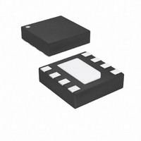
ATTINY9-MAHR Atmel, ATTINY9-MAHR Datasheet - Page 102

ATTINY9-MAHR
Manufacturer Part Number
ATTINY9-MAHR
Description
IC MCU AVR 1K FLASH 8UDFN
Manufacturer
Atmel
Series
AVR® ATtinyr
Datasheet
1.ATTINY9-MAHR.pdf
(169 pages)
Specifications of ATTINY9-MAHR
Package / Case
8-UDFN Exposed Pad
Voltage - Supply (vcc/vdd)
1.8 V ~ 5.5 V
Operating Temperature
-40°C ~ 85°C
Speed
12MHz
Number Of I /o
4
Core Processor
AVR
Program Memory Type
FLASH
Ram Size
32 x 8
Program Memory Size
1KB (1K x 8)
Oscillator Type
Internal
Peripherals
POR, PWM, WDT
Core Size
8-Bit
Lead Free Status / RoHS Status
Lead free / RoHS Compliant
Eeprom Size
-
Data Converters
-
Connectivity
-
Lead Free Status / Rohs Status
Details
Available stocks
Company
Part Number
Manufacturer
Quantity
Price
Company:
Part Number:
ATTINY9-MAHR
Manufacturer:
ST
Quantity:
101
- Current page: 102 of 169
- Download datasheet (5Mb)
14.4.1
14.4.2
102
ATtiny4/5/9/10
Message format
Exception Handling and Synchronisation
The TPI access layer controls the character transfer direction on the TPI physical layer. It also
handles the recovery from the error state after exception.
The Control and Status Space (CSS) of the Tiny Programming Interface is allocated for control
and status registers in the TPI access Layer. The CSS consist of registers directly involved in
the operation of the TPI itself. These register are accessible using the SLDCS and SSTCS
instructions.
The access layer can also access the data space, either directly or indirectly using the Pointer
Register (PR) as the address pointer. The data space is accessible using the SLD, SST, SIN
and SOUT instructions. The address pointer can be stored in the Pointer Register using the
SLDPR instruction.
Each message comprises an instruction followed by one or more byte operands. The instruction
is always sent by the external programmer. Depending on the instruction all the following oper-
ands are sent either by the external programmer or by the TPI.
The messages can be categorized in two types based on the instruction, as follows:
All the instructions except the SKEY instruction require the instruction to be followed by one byte
operand. The SKEY instruction requires 8 byte operands. For more information, see the TPI
instruction set on
Several situations are considered exceptions from normal operation of the TPI. When the TPI
physical layer is in receive mode, these exceptions are:
When the TPI physical layer is in transmit mode, the possible exceptions are:
All these exceptions are signalized to the TPI access layer. The access layer responds to an
exception by aborting any on-going operation and enters the error state. The access layer will
stay in the error state until a BREAK character has been received, after which it is taken back to
its default state. As a consequence, the external programmer can always synchronize the proto-
col by simply transmitting two successive BREAK characters.
• Write messages. A write message is a request to write data. The write message is sent
• Read messages. A read message is a request to read data. The TPI reacts to the request by
• The TPI physical layer detects a parity error.
• The TPI physical layer detects a frame error.
• The TPI physical layer recognizes a BREAK character.
• The TPI physical layer detects a data collision.
entirely by the external programmer. This message type is used with the SSTCS, SST,
STPR, SOUT and SKEY instructions.
sending the byte operands. This message type is used with the SLDCS, SLD and SIN
instructions.
page
103.
8127D–AVR–02/10
Related parts for ATTINY9-MAHR
Image
Part Number
Description
Manufacturer
Datasheet
Request
R

Part Number:
Description:
Manufacturer:
Atmel Corporation
Datasheet:

Part Number:
Description:
IC MCU AVR 1KB FLASH SOT-23-6
Manufacturer:
Atmel
Datasheet:

Part Number:
Description:
IC MCU AVR 1KB FLASH SOT-23-6
Manufacturer:
Atmel
Datasheet:

Part Number:
Description:
IC MCU AVR 1K FLASH 8UDFN
Manufacturer:
Atmel
Datasheet:

Part Number:
Description:
DEV KIT FOR AVR/AVR32
Manufacturer:
Atmel
Datasheet:

Part Number:
Description:
INTERVAL AND WIPE/WASH WIPER CONTROL IC WITH DELAY
Manufacturer:
ATMEL Corporation
Datasheet:

Part Number:
Description:
Low-Voltage Voice-Switched IC for Hands-Free Operation
Manufacturer:
ATMEL Corporation
Datasheet:

Part Number:
Description:
MONOLITHIC INTEGRATED FEATUREPHONE CIRCUIT
Manufacturer:
ATMEL Corporation
Datasheet:

Part Number:
Description:
AM-FM Receiver IC U4255BM-M
Manufacturer:
ATMEL Corporation
Datasheet:

Part Number:
Description:
Monolithic Integrated Feature Phone Circuit
Manufacturer:
ATMEL Corporation
Datasheet:

Part Number:
Description:
Multistandard Video-IF and Quasi Parallel Sound Processing
Manufacturer:
ATMEL Corporation
Datasheet:

Part Number:
Description:
High-performance EE PLD
Manufacturer:
ATMEL Corporation
Datasheet:


