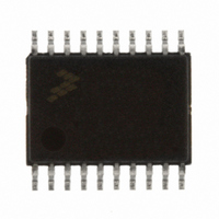
MC9S08EL16CTJ Freescale Semiconductor, MC9S08EL16CTJ Datasheet - Page 221
MC9S08EL16CTJ
Manufacturer Part Number
MC9S08EL16CTJ
Description
MCU 16KB FLASH SLIC 20TSSOP
Manufacturer
Freescale Semiconductor
Series
HCS08r
Datasheet
1.DEMO9S08EL32.pdf
(356 pages)
Specifications of MC9S08EL16CTJ
Core Processor
HCS08
Core Size
8-Bit
Speed
40MHz
Connectivity
I²C, LIN, SCI, SPI
Peripherals
LVD, POR, PWM, WDT
Number Of I /o
16
Program Memory Size
16KB (16K x 8)
Program Memory Type
FLASH
Eeprom Size
512 x 8
Ram Size
1K x 8
Voltage - Supply (vcc/vdd)
2.7 V ~ 5.5 V
Data Converters
A/D 12x10b
Oscillator Type
External
Operating Temperature
-40°C ~ 85°C
Package / Case
20-TSSOP
Processor Series
S08EL
Core
HCS08
Data Bus Width
8 bit
Data Ram Size
1 KB
Interface Type
SCI, SPI, I2C, SLIC
Maximum Clock Frequency
200 KHz
Number Of Programmable I/os
16
Number Of Timers
2
Operating Supply Voltage
5.5 V
Maximum Operating Temperature
+ 85 C
Mounting Style
SMD/SMT
3rd Party Development Tools
EWS08
Development Tools By Supplier
DEMO9S08EL32AUTO, DEMO9S08EL32
Minimum Operating Temperature
- 40 C
On-chip Adc
10 bit, 12 Channel
For Use With
DEMO9S08EL32 - BOARD DEMO FOR 9S08 EL MCUDEMO9S08EL32AUTO - DEMO BOARD EL32 AUTO
Lead Free Status / RoHS Status
Lead free / RoHS Compliant


1
12.6.15 Bit Error Detection and Physical Layer Delay
The bit error detection circuitry of the SLIC module monitors the received bits to determine if they match
the state of the corresponding transmitted bits. The sampling of the receive line takes place near the end
of the bit being transmitted, so as long as the total physical layer delay does not exceed 75% of one bit
time, bit error detection will work properly. For normal LIN bus speeds (<= 20 kbps), the physical layer
delay in the system is typically significantly lower than 75% of a bit time and bit error detection should
remain enabled by the user.
If the physical layer delay begins to exceed 75% of one bit time, the received bits begin to significantly
lag behind the transmitted bits. In this case, it's possible for the bit error detection circuitry to falsely
sample the delayed 'previous' bit on the receive pin rather than the current bit. It is the responsibility of the
user to determine if the total physical layer delay is large enough to require disabling the bit error detection
circuitry. This should only be required at speeds higher than allowed in normal LIN operations.
Freescale Semiconductor
Bit rates over 120,000 bits per second are not recommended for LIN communications, as physical layer delay between the
TX and RX pins can cause the stop bit of a byte to be mis-sampled as the last data bit. This could result in a byte framing
error.
(MHz)
clock
SLIC
20
18
16
14
12
10
2
8
6
4
2
Max Bit
(kbps)
312,500
281,250
250,000
218,750
187,500
156,250
125,000
Rate
15,625
93,750
62,500
31,250
Table 12-14. Digital Receive Filter Absolute Cutoff (Ideal Conditions)
RXFP = ÷8
RXFP = ÷4
Min Pulse
MC9S08EL32 Series and MC9S08SL16 Series Data Sheet, Rev. 3
Allowed
Width
(μs)
16.00
32.00
64.00
10.67
3.20
3.56
4.00
4.57
5.33
6.40
8.00
Max Bit
(kbps)
416,667
375,000
333,333
291,667
250,000
208,333
166,667
125,000
Rate
17,857
83,333
41,667
RXFP = ÷7
RXFP = ÷3
Min Pulse
Allowed
Width
(μs)
56.00
12.00
24.00
2.40
2.67
3.00
3.43
4.00
4.80
6.00
8.00
Max Bit
(kbps)
625,000
562,500
500,000
437,500
375,000
312,500
250,000
187,500
125,000
Rate
20,833
62,500
RXFP = ÷6
RXFP = ÷2
Min Pulse
Allowed
Width
(μs)
48.00
16.00
1.60
1.78
2.00
2.29
2.67
3.20
4.00
5.33
8.00
1,250,000
1,125,000
1,000,000
Max Bit
(kbps)
875,000
750,000
625,000
500,000
375,000
250,000
125,000
Rate
25,000
1
RXFP = ÷5
RXFP = ÷1
Min Pulse
Allowed
Width
(μs)
40.00
0.80
0.89
1.00
1.14
1.33
1.60
2.00
2.67
4.00
8.00
223
Related parts for MC9S08EL16CTJ
Image
Part Number
Description
Manufacturer
Datasheet
Request
R

Part Number:
Description:
Manufacturer:
Freescale Semiconductor, Inc
Datasheet:
Part Number:
Description:
Manufacturer:
Freescale Semiconductor, Inc
Datasheet:
Part Number:
Description:
Manufacturer:
Freescale Semiconductor, Inc
Datasheet:
Part Number:
Description:
Manufacturer:
Freescale Semiconductor, Inc
Datasheet:
Part Number:
Description:
Manufacturer:
Freescale Semiconductor, Inc
Datasheet:
Part Number:
Description:
Manufacturer:
Freescale Semiconductor, Inc
Datasheet:
Part Number:
Description:
Manufacturer:
Freescale Semiconductor, Inc
Datasheet:
Part Number:
Description:
Manufacturer:
Freescale Semiconductor, Inc
Datasheet:
Part Number:
Description:
Manufacturer:
Freescale Semiconductor, Inc
Datasheet:
Part Number:
Description:
Manufacturer:
Freescale Semiconductor, Inc
Datasheet:
Part Number:
Description:
Manufacturer:
Freescale Semiconductor, Inc
Datasheet:
Part Number:
Description:
Manufacturer:
Freescale Semiconductor, Inc
Datasheet:
Part Number:
Description:
Manufacturer:
Freescale Semiconductor, Inc
Datasheet:
Part Number:
Description:
Manufacturer:
Freescale Semiconductor, Inc
Datasheet:
Part Number:
Description:
Manufacturer:
Freescale Semiconductor, Inc
Datasheet: