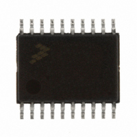
MC9S08EL16CTJ Freescale Semiconductor, MC9S08EL16CTJ Datasheet - Page 186

MC9S08EL16CTJ
Manufacturer Part Number
MC9S08EL16CTJ
Description
MCU 16KB FLASH SLIC 20TSSOP
Manufacturer
Freescale Semiconductor
Series
HCS08r
Datasheet
1.DEMO9S08EL32.pdf
(356 pages)
Specifications of MC9S08EL16CTJ
Core Processor
HCS08
Core Size
8-Bit
Speed
40MHz
Connectivity
I²C, LIN, SCI, SPI
Peripherals
LVD, POR, PWM, WDT
Number Of I /o
16
Program Memory Size
16KB (16K x 8)
Program Memory Type
FLASH
Eeprom Size
512 x 8
Ram Size
1K x 8
Voltage - Supply (vcc/vdd)
2.7 V ~ 5.5 V
Data Converters
A/D 12x10b
Oscillator Type
External
Operating Temperature
-40°C ~ 85°C
Package / Case
20-TSSOP
Processor Series
S08EL
Core
HCS08
Data Bus Width
8 bit
Data Ram Size
1 KB
Interface Type
SCI, SPI, I2C, SLIC
Maximum Clock Frequency
200 KHz
Number Of Programmable I/os
16
Number Of Timers
2
Operating Supply Voltage
5.5 V
Maximum Operating Temperature
+ 85 C
Mounting Style
SMD/SMT
3rd Party Development Tools
EWS08
Development Tools By Supplier
DEMO9S08EL32AUTO, DEMO9S08EL32
Minimum Operating Temperature
- 40 C
On-chip Adc
10 bit, 12 Channel
For Use With
DEMO9S08EL32 - BOARD DEMO FOR 9S08 EL MCUDEMO9S08EL32AUTO - DEMO BOARD EL32 AUTO
Lead Free Status / RoHS Status
Lead free / RoHS Compliant
- Current page: 186 of 356
- Download datasheet (9Mb)
12.1.2
Figure 12-2
12.1.2.1
This mode is entered from the reset mode whenever the SLIC module supply voltage V
minimum specified value for the SLIC module to guarantee operation. The SLIC module will be placed in
the reset mode by a system low-voltage reset (LVR) before being powered down. In this mode, the pin
input and output specifications are not guaranteed.
12.1.2.2
This mode is entered from the power off mode whenever the SLIC module supply voltage V
its minimum specified value (V
from entering an unknown state, the internal MCU reset is asserted while powering up the SLIC module.
SLIC reset mode is also entered from any other mode as soon as one of the MCU's possible reset sources
(e.g., LVR, POR, COP, RST pin, etc.) is asserted. SLIC reset mode may also be entered by the user
software by asserting the INITREQ bit. INITACK indicates whether the SLIC module is in the reset mode
as a result of writing INITREQ in SLCC1. While in the reset state the SLIC module clocks are stopped.
Clearing the INITREQ allows the SLIC to proceed and enter SLIC run mode (if SLCE is set). The module
188
INITREQ SET TO 1 IN
Modes of Operation
shows the modes in which the SLIC will operate.
(FROM ANY MODE)
SLCC1 REGISTER
Power Off
Reset
ANY MCU RESET SOURCE
SLCIE=1 and NETWORK ACTIVITY
(FROM ANY MODE)
SLIC STOP
MC9S08EL32 Series and MC9S08SL16 Series Data Sheet, Rev. 3
OR OTHER MCU
ASSERTED
WAKEUP
DD(MIN)
REQUESTED
V
DD
SLIC INIT
SLCE CLEARED IN
SLCC2 REGISTER
Figure 12-2. SLIC Operating Modes
<= V
(WAIT INSTRUCTION
STOP INSTRUCTION
AND SLCWCM = 1)
DD
) and some MCU reset source is asserted. To prevent the SLIC
(MIN)
(INITACK = 1)
SLIC DISABLED
POWER OFF
SLIC RESET
SLIC RUN
(WAIT INSTRUCTION
AND SLCWCM = 0)
SLCE SET IN SLCC2 REGISTER
NO MCU RESET SOURCE ASSERTED
INITREQ = 0; (INITACK = 0)
V
DD
MCU RESET SOURCE ASSERTED
> V
NETWORK ACTIVITY OR OTHER
DD
MCU WAKEUP
(MIN) AND ANY
SLIC WAIT
Freescale Semiconductor
DD
drops below its
DD
rises above
Related parts for MC9S08EL16CTJ
Image
Part Number
Description
Manufacturer
Datasheet
Request
R
Part Number:
Description:
Manufacturer:
Freescale Semiconductor, Inc
Datasheet:
Part Number:
Description:
Manufacturer:
Freescale Semiconductor, Inc
Datasheet:
Part Number:
Description:
Manufacturer:
Freescale Semiconductor, Inc
Datasheet:
Part Number:
Description:
Manufacturer:
Freescale Semiconductor, Inc
Datasheet:
Part Number:
Description:
Manufacturer:
Freescale Semiconductor, Inc
Datasheet:
Part Number:
Description:
Manufacturer:
Freescale Semiconductor, Inc
Datasheet:
Part Number:
Description:
Manufacturer:
Freescale Semiconductor, Inc
Datasheet:
Part Number:
Description:
Manufacturer:
Freescale Semiconductor, Inc
Datasheet:
Part Number:
Description:
Manufacturer:
Freescale Semiconductor, Inc
Datasheet:
Part Number:
Description:
Manufacturer:
Freescale Semiconductor, Inc
Datasheet:
Part Number:
Description:
Manufacturer:
Freescale Semiconductor, Inc
Datasheet:
Part Number:
Description:
Manufacturer:
Freescale Semiconductor, Inc
Datasheet:
Part Number:
Description:
Manufacturer:
Freescale Semiconductor, Inc
Datasheet:
Part Number:
Description:
Manufacturer:
Freescale Semiconductor, Inc
Datasheet:
Part Number:
Description:
Manufacturer:
Freescale Semiconductor, Inc
Datasheet:


