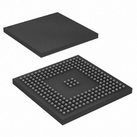
AT91SAM9RL64-CU Atmel, AT91SAM9RL64-CU Datasheet - Page 54

AT91SAM9RL64-CU
Manufacturer Part Number
AT91SAM9RL64-CU
Description
IC ARM9 MCU 217-LFBGA
Manufacturer
Atmel
Series
AT91SAMr
Specifications of AT91SAM9RL64-CU
Core Processor
ARM9
Core Size
16/32-Bit
Speed
240MHz
Connectivity
EBI/EMI, I²C, MMC, SPI, SSC, UART/USART, USB
Peripherals
AC'97, LCD, POR, PWM, WDT
Number Of I /o
118
Program Memory Size
32KB (32K x 8)
Program Memory Type
ROM
Ram Size
72K x 8
Voltage - Supply (vcc/vdd)
1.08 V ~ 1.32 V
Data Converters
A/D 6x10b
Oscillator Type
Internal
Operating Temperature
-40°C ~ 85°C
Package / Case
217-LFBGA
Processor Series
AT91SAMx
Core
ARM926EJ-S
Data Bus Width
32 bit
Data Ram Size
64 KB
Interface Type
2-Wire, SPI, SSC, USART
Maximum Clock Frequency
240 MHz
Number Of Programmable I/os
118
Number Of Timers
4
Maximum Operating Temperature
+ 85 C
Mounting Style
SMD/SMT
3rd Party Development Tools
JTRACE-ARM-2M, MDK-ARM, RL-ARM, ULINK2
Development Tools By Supplier
AT91SAM-ICE, AT91-ISP
Minimum Operating Temperature
- 40 C
On-chip Adc
10 bit, 6 Channel
Controller Family/series
AT91SAM9xxx
No. Of I/o's
118
Ram Memory Size
64KB
Cpu Speed
240MHz
No. Of Timers
1
Rohs Compliant
Yes
Package
217LFBGA
Device Core
ARM926EJ-S
Family Name
91S
Maximum Speed
240 MHz
Operating Supply Voltage
1.8|3.3 V
For Use With
AT91SAM9RL-EK - KIT EVAL FOR AT91SAM9RLAT91SAM-ICE - EMULATOR FOR AT91 ARM7/ARM9
Lead Free Status / RoHS Status
Lead free / RoHS Compliant
Eeprom Size
-
Lead Free Status / Rohs Status
Lead free / RoHS Compliant
Available stocks
Company
Part Number
Manufacturer
Quantity
Price
Company:
Part Number:
AT91SAM9RL64-CU
Manufacturer:
ATMEL
Quantity:
16
Company:
Part Number:
AT91SAM9RL64-CU
Manufacturer:
ATMEL
Quantity:
255
Part Number:
AT91SAM9RL64-CU
Manufacturer:
ATMEGL
Quantity:
20 000
- Current page: 54 of 903
- Download datasheet (13Mb)
12.3.7.2
54
Exception Types and Priorities
AT91SAM9R64/RL64 Preliminary
Exceptions
Figure 12-2. Status Register Format
Figure 12-2
The
leged mode. The types of exceptions are:
When an exception occurs, the banked version of R14 and the SPSR for the exception mode
are used to save the state.
More than one exception can happen at a time, therefore the ARM9EJ-S takes the arisen excep-
tions according to the following priority order:
• N: Negative, Z: Zero, C: Carry, and V: Overflow are the four ALU flags
• The Sticky Overflow (Q) flag can be set by certain multiply and fractional arithmetic
• The J bit in the CPSR indicates when the ARM9EJ-S core is in Jazelle state, where:
• Mode: five bits to encode the current processor mode
• Fast interrupt (FIQ)
• Normal interrupt (IRQ)
• Data and Prefetched aborts (Abort)
• Undefined instruction (Undefined)
• Software interrupt and Reset (Supervisor)
• Reset (highest priority)
• Data Abort
• FIQ
• IRQ
• Prefetch Abort
• BKPT, Undefined instruction, and Software Interrupt (SWI) (Lowest priority)
instructions like QADD, QDADD, QSUB, QDSUB, SMLAxy, and SMLAWy needed to achieve
DSP operations.
The Q flag is sticky in that, when set by an instruction, it remains set until explicitly cleared by
an MSR instruction writing to the CPSR. Instructions cannot execute conditionally on the
status of the Q flag.
ARM9EJ-S supports five types of exceptions. Each type drives the ARM9EJ-S in a privi-
– J = 0: The processor is in ARM or Thumb state, depending on the T bit
– J = 1: The processor is in Jazelle state.
shows the status register format, where:
N Z C V Q
31 30 29 28 27
24
J
Jazelle state bit
Reserved
Sticky Overflow
Overflow
Carry/Borrow/Extend
Zero
Negative/Less than
Reserved
I F T
7 6 5
Mode
0
Mode bits
Thumb state bit
FIQ disable
IRQ disable
6289C–ATARM–28-May-09
Related parts for AT91SAM9RL64-CU
Image
Part Number
Description
Manufacturer
Datasheet
Request
R

Part Number:
Description:
MCU, MPU & DSP Development Tools KICKSTART KIT FOR AT91SAM9 PLUS
Manufacturer:
IAR Systems

Part Number:
Description:
DEV KIT FOR AVR/AVR32
Manufacturer:
Atmel
Datasheet:

Part Number:
Description:
INTERVAL AND WIPE/WASH WIPER CONTROL IC WITH DELAY
Manufacturer:
ATMEL Corporation
Datasheet:

Part Number:
Description:
Low-Voltage Voice-Switched IC for Hands-Free Operation
Manufacturer:
ATMEL Corporation
Datasheet:

Part Number:
Description:
MONOLITHIC INTEGRATED FEATUREPHONE CIRCUIT
Manufacturer:
ATMEL Corporation
Datasheet:

Part Number:
Description:
AM-FM Receiver IC U4255BM-M
Manufacturer:
ATMEL Corporation
Datasheet:

Part Number:
Description:
Monolithic Integrated Feature Phone Circuit
Manufacturer:
ATMEL Corporation
Datasheet:

Part Number:
Description:
Multistandard Video-IF and Quasi Parallel Sound Processing
Manufacturer:
ATMEL Corporation
Datasheet:

Part Number:
Description:
High-performance EE PLD
Manufacturer:
ATMEL Corporation
Datasheet:

Part Number:
Description:
8-bit Flash Microcontroller
Manufacturer:
ATMEL Corporation
Datasheet:

Part Number:
Description:
2-Wire Serial EEPROM
Manufacturer:
ATMEL Corporation
Datasheet:


