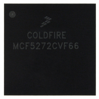
MCF5272CVF66 Freescale Semiconductor, MCF5272CVF66 Datasheet - Page 294

MCF5272CVF66
Manufacturer Part Number
MCF5272CVF66
Description
IC MPU 32BIT 66MHZ 196-MAPBGA
Manufacturer
Freescale Semiconductor
Series
MCF527xr
Specifications of MCF5272CVF66
Core Processor
Coldfire V2
Core Size
32-Bit
Speed
66MHz
Connectivity
EBI/EMI, Ethernet, I²C, SPI, UART/USART, USB
Peripherals
DMA, WDT
Number Of I /o
32
Program Memory Size
16KB (4K x 32)
Program Memory Type
ROM
Ram Size
1K x 32
Voltage - Supply (vcc/vdd)
3 V ~ 3.6 V
Oscillator Type
External
Operating Temperature
-40°C ~ 85°C
Package / Case
196-MAPBGA
Family Name
MCF5xxx
Device Core
ColdFire
Device Core Size
32b
Frequency (max)
66MHz
Instruction Set Architecture
RISC
Supply Voltage 1 (typ)
3.3V
Operating Temp Range
-40C to 85C
Operating Temperature Classification
Industrial
Mounting
Surface Mount
Pin Count
196
Package Type
MA-BGA
Lead Free Status / RoHS Status
Contains lead / RoHS non-compliant
Eeprom Size
-
Data Converters
-
Lead Free Status / Rohs Status
Not Compliant
Available stocks
Company
Part Number
Manufacturer
Quantity
Price
Company:
Part Number:
MCF5272CVF66
Manufacturer:
Freescale Semiconductor
Quantity:
10 000
Part Number:
MCF5272CVF66
Manufacturer:
FREESCALE
Quantity:
20 000
Company:
Part Number:
MCF5272CVF66 K75N
Manufacturer:
ST
Quantity:
18
Company:
Part Number:
MCF5272CVF66J
Manufacturer:
Freescale Semiconductor
Quantity:
10 000
- Current page: 294 of 544
- Download datasheet (7Mb)
Universal Serial Bus (USB)
12.5
The recommended line interface is shown in
pull-up resistor is optional.
12.5.1
The USB specification requires that a pull-up resistor must be placed on the D+ signal for the upstream
hub to detect attachment of a full-speed device. The user may optionally want to control the attach/detach
detection by software instead of only at power on and off. With software control of the pull-up resistor, the
user has unlimited time to initialize the USB module. The software controlled pull-up resistor can be
implemented with only a few discrete components. The recommended circuit for implementing software
control of the pull-up resistor is shown in
12.5.2
The device has input protection on all pins and may source or sink a limited amount of current without
damage.
The most important considerations for PCB layout deal with noise: noise on the power supply, noise
generated by the digital circuitry on the device, and noise resulting from coupling digital signals into the
analog signals. The best PCB layout methods to prevent noise–induced problems are as follows:
12-36
•
•
•
Keep digital signals as far away from analog signals (D+ and D-) as possible.
Use short, low inductance traces for the analog circuitry to reduce inductive, capacitive, and radio
frequency noise sensitivities.
Use short, low inductance traces for digital circuitry to reduce inductive, capacitive, and radio
frequency radiated noise.
MCF5272
Line Interface
Attachment Detection
PCB Layout Recommendations
GP I/O pin
MCF5272 ColdFire
USB_D+
USB_D-
Figure 12-24. Recommended USB Line Interface
100Ω
33Ω
33Ω
®
Integrated Microprocessor User’s Manual, Rev. 3
Figure
1kΩ
Figure
12-24.
3.3 V
12-24. The transistor used to control the 1.5–kΩ
1.5kΩ±5%
Vbus
D+
D–
GND
USB
Series B
Receptacle
Freescale Semiconductor
Related parts for MCF5272CVF66
Image
Part Number
Description
Manufacturer
Datasheet
Request
R
Part Number:
Description:
Mcf5272 Coldfire Integrated Microprocessor User
Manufacturer:
Freescale Semiconductor, Inc
Datasheet:

Part Number:
Description:
MCF5272 Interrupt Service Routine for the Physical Layer Interface Controller
Manufacturer:
Freescale Semiconductor / Motorola
Datasheet:
Part Number:
Description:
Manufacturer:
Freescale Semiconductor, Inc
Datasheet:
Part Number:
Description:
Manufacturer:
Freescale Semiconductor, Inc
Datasheet:
Part Number:
Description:
Manufacturer:
Freescale Semiconductor, Inc
Datasheet:
Part Number:
Description:
Manufacturer:
Freescale Semiconductor, Inc
Datasheet:
Part Number:
Description:
Manufacturer:
Freescale Semiconductor, Inc
Datasheet:
Part Number:
Description:
Manufacturer:
Freescale Semiconductor, Inc
Datasheet:
Part Number:
Description:
Manufacturer:
Freescale Semiconductor, Inc
Datasheet:
Part Number:
Description:
Manufacturer:
Freescale Semiconductor, Inc
Datasheet:
Part Number:
Description:
Manufacturer:
Freescale Semiconductor, Inc
Datasheet:
Part Number:
Description:
Manufacturer:
Freescale Semiconductor, Inc
Datasheet:
Part Number:
Description:
Manufacturer:
Freescale Semiconductor, Inc
Datasheet:
Part Number:
Description:
Manufacturer:
Freescale Semiconductor, Inc
Datasheet:
Part Number:
Description:
Manufacturer:
Freescale Semiconductor, Inc
Datasheet:


