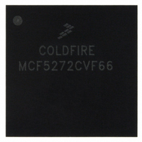
MCF5272CVF66 Freescale Semiconductor, MCF5272CVF66 Datasheet - Page 10

MCF5272CVF66
Manufacturer Part Number
MCF5272CVF66
Description
IC MPU 32BIT 66MHZ 196-MAPBGA
Manufacturer
Freescale Semiconductor
Series
MCF527xr
Specifications of MCF5272CVF66
Core Processor
Coldfire V2
Core Size
32-Bit
Speed
66MHz
Connectivity
EBI/EMI, Ethernet, I²C, SPI, UART/USART, USB
Peripherals
DMA, WDT
Number Of I /o
32
Program Memory Size
16KB (4K x 32)
Program Memory Type
ROM
Ram Size
1K x 32
Voltage - Supply (vcc/vdd)
3 V ~ 3.6 V
Oscillator Type
External
Operating Temperature
-40°C ~ 85°C
Package / Case
196-MAPBGA
Family Name
MCF5xxx
Device Core
ColdFire
Device Core Size
32b
Frequency (max)
66MHz
Instruction Set Architecture
RISC
Supply Voltage 1 (typ)
3.3V
Operating Temp Range
-40C to 85C
Operating Temperature Classification
Industrial
Mounting
Surface Mount
Pin Count
196
Package Type
MA-BGA
Lead Free Status / RoHS Status
Contains lead / RoHS non-compliant
Eeprom Size
-
Data Converters
-
Lead Free Status / Rohs Status
Not Compliant
Available stocks
Company
Part Number
Manufacturer
Quantity
Price
Company:
Part Number:
MCF5272CVF66
Manufacturer:
Freescale Semiconductor
Quantity:
10 000
Part Number:
MCF5272CVF66
Manufacturer:
FREESCALE
Quantity:
20 000
Company:
Part Number:
MCF5272CVF66 K75N
Manufacturer:
ST
Quantity:
18
Company:
Part Number:
MCF5272CVF66J
Manufacturer:
Freescale Semiconductor
Quantity:
10 000
- Current page: 10 of 544
- Download datasheet (7Mb)
Figure
Number
16-3
16-4
16-5
16-6
16-7
16-8
16-9
16-10
16-11
16-12
16-13
16-14
16-15
16-16
16-17
16-18
16-19
16-20
16-21
16-22
16-23
16-24
16-25
16-26
16-27
16-28
16-29
16-30
16-31
17-1
17-2
17-3
17-4
17-5
17-6
17-7
18-1
18-2
18-3
18-4
19-1
20-1
20-2
20-3
x
UART Mode Register 2 (UMR2n) ......................................................................................... 16-6
UART Status Registers (USRn) ............................................................................................ 16-7
UART Clock-Select Registers (UCSRn) ............................................................................... 16-8
UART Command Registers (UCRn) ..................................................................................... 16-9
UART Receiver Buffer (URBn)............................................................................................ 16-10
UART Transmitter Buffers (UTBn) ...................................................................................... 16-11
UART Input Port Change Registers (UIPCRn) ................................................................... 16-11
UART Auxiliary Control Registers (UACRn) ....................................................................... 16-12
UART Interrupt Status/Mask Registers (UISRn/UIMRn)..................................................... 16-13
UART Divider Upper Registers (UDUn) .............................................................................. 16-14
UART Divider Lower Registers (UDLn)............................................................................... 16-14
UART Autobaud Upper Registers (UABUn)........................................................................ 16-14
UART Autobaud Lower Registers (UABLn) ........................................................................ 16-14
UART Transmitter FIFO Registers (UTFn) ......................................................................... 16-15
UART Receiver FIFO Registers (URFn) ............................................................................. 16-16
UART Fractional Precision Divider Control Registers (UFPDn).......................................... 16-17
UART Input Port Registers (UIPn) ...................................................................................... 16-17
UART Output Port Command Registers (UOP1/UOP0) ..................................................... 16-18
UART Block Diagram Showing External and Internal Interface Signals ............................. 16-18
UART/RS-232 Interface ...................................................................................................... 16-19
Clocking Source Diagram ................................................................................................... 16-20
Transmitter and Receiver Functional Diagram.................................................................... 16-22
Transmitter Timing .............................................................................................................. 16-23
Receiver Timing .................................................................................................................. 16-24
Automatic Echo ................................................................................................................... 16-27
Local Loop-Back ................................................................................................................. 16-27
Remote Loop-Back ............................................................................................................. 16-28
Multidrop Mode Timing Diagram ......................................................................................... 16-29
UART Mode Programming Flowchart (Sheet 1 of 5) .......................................................... 16-30
Port A Control Register (PACNT).......................................................................................... 17-3
Port B Control Register (PBCNT).......................................................................................... 17-5
Port D Control Register (PDCNT) ......................................................................................... 17-8
Port A Data Direction Register (PADDR) ............................................................................ 17-10
Port B Data Direction Register (PBDDR) ............................................................................ 17-10
Port C Data Direction Register (PCDDR)............................................................................ 17-11
Port x Data Register (PADAT, PBDAT, and PCDAT) ......................................................... 17-11
PWM Block Diagram (3 Identical Modules)........................................................................... 18-1
PWM Control Registers (PWCRn) ........................................................................................ 18-3
PWM Width Register (PWWDn)............................................................................................ 18-4
PWM Waveform Examples (PWCRn[EN] = 1)...................................................................... 18-4
MCF5272 Block Diagram with Signal Interfaces................................................................... 19-2
Internal Operand Representation.......................................................................................... 20-5
MCF5272 Interface to Various Port Sizes............................................................................. 20-5
Longword Read; EBI = 00; 32-Bit Port; Internal Termination................................................ 20-8
MCF5272 ColdFire
List of Figures (Continued)
®
Integrated Microprocessor User’s Manual, Rev. 3
Title
Freescale Semiconductor
Number
Page
Related parts for MCF5272CVF66
Image
Part Number
Description
Manufacturer
Datasheet
Request
R
Part Number:
Description:
Mcf5272 Coldfire Integrated Microprocessor User
Manufacturer:
Freescale Semiconductor, Inc
Datasheet:

Part Number:
Description:
MCF5272 Interrupt Service Routine for the Physical Layer Interface Controller
Manufacturer:
Freescale Semiconductor / Motorola
Datasheet:
Part Number:
Description:
Manufacturer:
Freescale Semiconductor, Inc
Datasheet:
Part Number:
Description:
Manufacturer:
Freescale Semiconductor, Inc
Datasheet:
Part Number:
Description:
Manufacturer:
Freescale Semiconductor, Inc
Datasheet:
Part Number:
Description:
Manufacturer:
Freescale Semiconductor, Inc
Datasheet:
Part Number:
Description:
Manufacturer:
Freescale Semiconductor, Inc
Datasheet:
Part Number:
Description:
Manufacturer:
Freescale Semiconductor, Inc
Datasheet:
Part Number:
Description:
Manufacturer:
Freescale Semiconductor, Inc
Datasheet:
Part Number:
Description:
Manufacturer:
Freescale Semiconductor, Inc
Datasheet:
Part Number:
Description:
Manufacturer:
Freescale Semiconductor, Inc
Datasheet:
Part Number:
Description:
Manufacturer:
Freescale Semiconductor, Inc
Datasheet:
Part Number:
Description:
Manufacturer:
Freescale Semiconductor, Inc
Datasheet:
Part Number:
Description:
Manufacturer:
Freescale Semiconductor, Inc
Datasheet:
Part Number:
Description:
Manufacturer:
Freescale Semiconductor, Inc
Datasheet:


