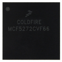
MCF5272CVF66 Freescale Semiconductor, MCF5272CVF66 Datasheet - Page 26

MCF5272CVF66
Manufacturer Part Number
MCF5272CVF66
Description
IC MPU 32BIT 66MHZ 196-MAPBGA
Manufacturer
Freescale Semiconductor
Series
MCF527xr
Specifications of MCF5272CVF66
Core Processor
Coldfire V2
Core Size
32-Bit
Speed
66MHz
Connectivity
EBI/EMI, Ethernet, I²C, SPI, UART/USART, USB
Peripherals
DMA, WDT
Number Of I /o
32
Program Memory Size
16KB (4K x 32)
Program Memory Type
ROM
Ram Size
1K x 32
Voltage - Supply (vcc/vdd)
3 V ~ 3.6 V
Oscillator Type
External
Operating Temperature
-40°C ~ 85°C
Package / Case
196-MAPBGA
Family Name
MCF5xxx
Device Core
ColdFire
Device Core Size
32b
Frequency (max)
66MHz
Instruction Set Architecture
RISC
Supply Voltage 1 (typ)
3.3V
Operating Temp Range
-40C to 85C
Operating Temperature Classification
Industrial
Mounting
Surface Mount
Pin Count
196
Package Type
MA-BGA
Lead Free Status / RoHS Status
Contains lead / RoHS non-compliant
Eeprom Size
-
Data Converters
-
Lead Free Status / Rohs Status
Not Compliant
Available stocks
Company
Part Number
Manufacturer
Quantity
Price
Company:
Part Number:
MCF5272CVF66
Manufacturer:
Freescale Semiconductor
Quantity:
10 000
Part Number:
MCF5272CVF66
Manufacturer:
FREESCALE
Quantity:
20 000
Company:
Part Number:
MCF5272CVF66 K75N
Manufacturer:
ST
Quantity:
18
Company:
Part Number:
MCF5272CVF66J
Manufacturer:
Freescale Semiconductor
Quantity:
10 000
- Current page: 26 of 544
- Download datasheet (7Mb)
Paragraph
Number
19.7 CPU Clock and Reset Signals .................................................................................................. 19-23
19.8 Interrupt Request Inputs (INT[6:1]) ......................................................................................... 19-23
19.9 General-Purpose I/O (GPIO) Ports .......................................................................................... 19-24
19.10 UART0 Module Signals and PB[4:0] .................................................................................... 19-24
19.11 USB Module Signals and PA[6:0] ......................................................................................... 19-25
19.12 Timer Module Signals ............................................................................................................ 19-27
xxvi
19.6.2 Byte Strobes (BS[3:0]) ................................................................................................. 19-20
19.6.3 Read/Write (R/W) ......................................................................................................... 19-21
19.6.4 Transfer Acknowledge (TA/PB5) ................................................................................. 19-22
19.6.5 Hi-Z .............................................................................................................................. 19-22
19.6.6 Bypass ........................................................................................................................... 19-22
19.6.7 SDRAM Row Address Strobe (RAS0) ........................................................................ 19-22
19.6.8 SDRAM Column Address Strobe (CAS0) ................................................................... 19-22
19.6.9 SDRAM Clock (SDCLK) ............................................................................................. 19-22
19.6.10 SDRAM Write Enable (SDWE) ................................................................................. 19-22
19.6.11 SDRAM Clock Enable (SDCLKE) ............................................................................ 19-22
19.6.12 SDRAM Bank Selects (SDBA[1:0]) .......................................................................... 19-23
19.6.13 SDRAM Row Address 10 (A10)/A10 Precharge (A10_PRECHG) .......................... 19-23
19.7.1 RSTI ............................................................................................................................. 19-23
19.7.2 DRESETEN .................................................................................................................. 19-23
19.7.3 CPU External Clock (CLKIN) ..................................................................................... 19-23
19.7.4 Reset Output (RSTO) ................................................................................................... 19-23
19.10.1 Transmit Serial Data Output (URT0_TxD/PB0) ........................................................ 19-24
19.10.2 Receive Serial Data Input (URT0_RxD/PB1) ............................................................ 19-25
19.10.3 Clear-to-Send (URT0_CTS/PB2) ............................................................................... 19-25
19.10.4 Request to Send (URT0_RTS/PB3) ............................................................................ 19-25
19.10.5 Clock (URT0_CLK/PB4) ........................................................................................... 19-25
19.11.1 USB Transmit Serial Data Output (USB_TP/PA0) .................................................... 19-25
19.11.2 USB Receive Serial Data Input (USB_RP/PA1) ........................................................ 19-25
19.11.3 USB Receive Data Negative (USB_RN/PA2) ............................................................ 19-25
19.11.4 USB Transmit Data Negative (USB_TN/PA3) ........................................................... 19-26
19.11.5 USB Suspend Driver (USB_SUSP/PA4) .................................................................... 19-26
19.11.6 USB Transmitter Output Enable (USB_TxEN/PA5) .................................................. 19-26
19.11.7 USB Rx Data Output (USB_RxD/PA6) ..................................................................... 19-26
19.11.8 USB_D+ and USB_D- ................................................................................................ 19-26
19.11.9 USB_CLK .................................................................................................................. 19-26
19.11.10 INT1/USB Wake-on-Ring (USB_WOR) ................................................................. 19-26
19.12.1 Timer Input 0 (TIN0) .................................................................................................. 19-27
19.12.2 Timer Output (TOUT0)/PB7 ...................................................................................... 19-27
19.12.3 Timer Input 1 (TIN1)/PWM Mode Output 2 (PWM_OUT2) .................................... 19-27
19.12.4 Timer Output 1 (TOUT1)/PWM Mode Output 1 (PWM_OUT1) .............................. 19-27
MCF5272 ColdFire
Table of Contents (Continued)
®
Integrated Microprocessor User’s Manual, Rev. 3
Title
Freescale Semiconductor
Number
Page
Related parts for MCF5272CVF66
Image
Part Number
Description
Manufacturer
Datasheet
Request
R
Part Number:
Description:
Mcf5272 Coldfire Integrated Microprocessor User
Manufacturer:
Freescale Semiconductor, Inc
Datasheet:

Part Number:
Description:
MCF5272 Interrupt Service Routine for the Physical Layer Interface Controller
Manufacturer:
Freescale Semiconductor / Motorola
Datasheet:
Part Number:
Description:
Manufacturer:
Freescale Semiconductor, Inc
Datasheet:
Part Number:
Description:
Manufacturer:
Freescale Semiconductor, Inc
Datasheet:
Part Number:
Description:
Manufacturer:
Freescale Semiconductor, Inc
Datasheet:
Part Number:
Description:
Manufacturer:
Freescale Semiconductor, Inc
Datasheet:
Part Number:
Description:
Manufacturer:
Freescale Semiconductor, Inc
Datasheet:
Part Number:
Description:
Manufacturer:
Freescale Semiconductor, Inc
Datasheet:
Part Number:
Description:
Manufacturer:
Freescale Semiconductor, Inc
Datasheet:
Part Number:
Description:
Manufacturer:
Freescale Semiconductor, Inc
Datasheet:
Part Number:
Description:
Manufacturer:
Freescale Semiconductor, Inc
Datasheet:
Part Number:
Description:
Manufacturer:
Freescale Semiconductor, Inc
Datasheet:
Part Number:
Description:
Manufacturer:
Freescale Semiconductor, Inc
Datasheet:
Part Number:
Description:
Manufacturer:
Freescale Semiconductor, Inc
Datasheet:
Part Number:
Description:
Manufacturer:
Freescale Semiconductor, Inc
Datasheet:


