DEMO9S08JM16 Freescale Semiconductor, DEMO9S08JM16 Datasheet - Page 319
DEMO9S08JM16
Manufacturer Part Number
DEMO9S08JM16
Description
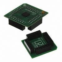
BOARD DEMO FOR JM16 FAMI
Manufacturer
Freescale Semiconductor
Type
MCUr
Datasheets
1.DEMO9S08JM16.pdf
(47 pages)
2.DEMO9S08JM16.pdf
(5 pages)
3.DEMO9S08JM16.pdf
(4 pages)
4.DEMO9S08JM16.pdf
(386 pages)
Specifications of DEMO9S08JM16
Contents
Board with Daughter card, Cable, Documentation, Mini-AB USB Kit
Processor To Be Evaluated
MC9S08JM16
Data Bus Width
8 bit
Interface Type
USB
Silicon Manufacturer
Freescale
Core Architecture
HCS08
Core Sub-architecture
HCS08
Silicon Core Number
MC9S08
Silicon Family Name
Flexis - S08JM
Rohs Compliant
Yes
For Use With/related Products
MC9S08JM16
Lead Free Status / RoHS Status
Lead free / RoHS Compliant


17.4.3
When the USB module transmits or receives data, it will first compute the BDT address based on the
endpoint number, data direction, and which buffer is being used (even or odd), then it will read the BD.
Once the BD has been read, and if the OWN bit equals 1, the serial interface engine (SIE) will transfer the
packet data to or receive the packet data from the buffer pointed to by the EPADR field of the BD. When
the USB TOKEN is complete, the USB module will update the BDT and change the OWN bit to 0.
The STAT register is updated and the TOKDNE interrupt is set. When the microcontroller processes the
TOKDNE interrupt, it reads the status register. This gives the microcontroller all the information it needs
to process the endpoint. At this point the microcontroller can allocate a new BD, so additional USB data
can be transmitted or received for that endpoint, and it can process the previous BD.
a timeline for how a typical USB token would be processed.
Freescale Semiconductor
EPADR[9:4]
BC[7:0]
Field
USB Transactions
Byte Count — The Byte Count bits represent the 8-bit byte count. The USB module serial interface engine
(SIE) will change this field upon the completion of a RX transfer with the byte count of the data received. Note
that while USB supports packets as large as 1023 bytes for isochronous endpoints, this module limits packet
size to 64 bytes.
Endpoint Address— The endpoint address bits represent the upper 6 bits of the 10-bit buffer address within
the module’s local USB RAM. Bits [3:0] of EPADR are always zero, therefore the address of the buffer must
always start on a 16-byte aligned address within the local RAM. These bits are unchanged by the USB module.
This is NOT the address of the memory on the system bus. EPADR is relative to the start of the local USB RAM.
Table 17-22. Buffer Descriptor Table Fields (continued)
MC9S08JM16 Series Data Sheet, Rev. 2
Description
Universal Serial Bus Device Controller (S08USBV1)
Figure 17-20
shows
319
Related parts for DEMO9S08JM16
Image
Part Number
Description
Manufacturer
Datasheet
Request
R

Part Number:
Description:
Manufacturer:
Freescale Semiconductor, Inc
Datasheet:
Part Number:
Description:
Manufacturer:
Freescale Semiconductor, Inc
Datasheet:
Part Number:
Description:
Manufacturer:
Freescale Semiconductor, Inc
Datasheet:
Part Number:
Description:
Manufacturer:
Freescale Semiconductor, Inc
Datasheet:
Part Number:
Description:
Manufacturer:
Freescale Semiconductor, Inc
Datasheet:
Part Number:
Description:
Manufacturer:
Freescale Semiconductor, Inc
Datasheet:
Part Number:
Description:
Manufacturer:
Freescale Semiconductor, Inc
Datasheet:
Part Number:
Description:
Manufacturer:
Freescale Semiconductor, Inc
Datasheet:
Part Number:
Description:
Manufacturer:
Freescale Semiconductor, Inc
Datasheet:
Part Number:
Description:
Manufacturer:
Freescale Semiconductor, Inc
Datasheet:
Part Number:
Description:
Manufacturer:
Freescale Semiconductor, Inc
Datasheet:
Part Number:
Description:
Manufacturer:
Freescale Semiconductor, Inc
Datasheet:
Part Number:
Description:
Manufacturer:
Freescale Semiconductor, Inc
Datasheet:
Part Number:
Description:
Manufacturer:
Freescale Semiconductor, Inc
Datasheet:
Part Number:
Description:
Manufacturer:
Freescale Semiconductor, Inc
Datasheet: