DEMO9S08JM16 Freescale Semiconductor, DEMO9S08JM16 Datasheet - Page 124
DEMO9S08JM16
Manufacturer Part Number
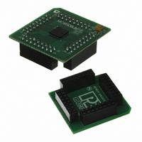
DEMO9S08JM16
Description
BOARD DEMO FOR JM16 FAMI
Manufacturer
Freescale Semiconductor
Type
MCUr
Datasheets
1.DEMO9S08JM16.pdf
(47 pages)
2.DEMO9S08JM16.pdf
(5 pages)
3.DEMO9S08JM16.pdf
(4 pages)
4.DEMO9S08JM16.pdf
(386 pages)
Specifications of DEMO9S08JM16
Contents
Board with Daughter card, Cable, Documentation, Mini-AB USB Kit
Processor To Be Evaluated
MC9S08JM16
Data Bus Width
8 bit
Interface Type
USB
Silicon Manufacturer
Freescale
Core Architecture
HCS08
Core Sub-architecture
HCS08
Silicon Core Number
MC9S08
Silicon Family Name
Flexis - S08JM
Rohs Compliant
Yes
For Use With/related Products
MC9S08JM16
Lead Free Status / RoHS Status
Lead free / RoHS Compliant


Keyboard Interrupts (S08KBIV2)
8.4
This on-chip peripheral module is called a keyboard interrupt (KBI) module because originally it was
designed to simplify the connection and use of row-column matrices of keyboard switches. However, these
inputs are also useful as extra external interrupt inputs and as an external means of waking the MCU from
stop or wait low-power modes.
The KBI module allows up to eight pins to act as additional interrupt sources. Writing to the KBIPEn bits
in the keyboard interrupt pin enable register (KBIPE) independently enables or disables each KBI pin.
Each KBI pin can be configured as edge sensitive or edge and level sensitive based on the KBMOD bit in
the keyboard interrupt status and control register (KBISC). Edge sensitive can be software programmed to
be either falling or rising; the level can be either low or high. The polarity of the edge or edge and level
sensitivity is selected using the KBEDGn bits in the keyboard interrupt edge select register (KBIES).
8.4.1
Synchronous logic is used to detect edges. A falling edge is detected when an enabled keyboard interrupt
(KBIPEn=1) input signal is seen as a logic 1 (the deasserted level) during one bus cycle and then a logic 0
(the asserted level) during the next cycle. A rising edge is detected when the input signal is seen as a logic
0 (the deasserted level) during one bus cycle and then a logic 1 (the asserted level) during the next
cycle.Before the first edge is detected, all enabled keyboard interrupt input signals must be at the
deasserted logic levels. After any edge is detected, all enabled keyboard interrupt input signals must return
to the deasserted level before any new edge can be detected.
A valid edge on an enabled KBI pin will set KBF in KBISC. If KBIE in KBISC is set, an interrupt request
will be presented to the CPU. Clearing of KBF is accomplished by writing a 1 to KBACK in KBISC.
8.4.2
A valid edge or level on an enabled KBI pin will set KBF in KBISC. If KBIE in KBISC is set, an interrupt
request will be presented to the CPU. Clearing of KBF is accomplished by writing a 1 to KBACK in
124
KBEDGn
Field
7:0
Reset:
Functional Description
Keyboard Edge Selects — Each of the KBEDGn bits selects the falling edge/low level or rising edge/high level
function of the corresponding pin).
0 Falling edge/low level.
1 Rising edge/high level.
W
Edge Only Sensitivity
Edge and Level Sensitivity
R
KBEDG7
0
7
KBEDG6
0
6
Table 8-4. KBIES Register Field Descriptions
Figure 8-5. KBI Edge Select Register
MC9S08JM16 Series Data Sheet, Rev. 2
KBEDG5
5
0
KBEDG4
0
4
Description
KBEDG3
0
3
KBEDG2
0
2
KBEDG1
0
1
Freescale Semiconductor
KBEDG0
0
0
Related parts for DEMO9S08JM16
Image
Part Number
Description
Manufacturer
Datasheet
Request
R

Part Number:
Description:
Manufacturer:
Freescale Semiconductor, Inc
Datasheet:
Part Number:
Description:
Manufacturer:
Freescale Semiconductor, Inc
Datasheet:
Part Number:
Description:
Manufacturer:
Freescale Semiconductor, Inc
Datasheet:
Part Number:
Description:
Manufacturer:
Freescale Semiconductor, Inc
Datasheet:
Part Number:
Description:
Manufacturer:
Freescale Semiconductor, Inc
Datasheet:
Part Number:
Description:
Manufacturer:
Freescale Semiconductor, Inc
Datasheet:
Part Number:
Description:
Manufacturer:
Freescale Semiconductor, Inc
Datasheet:
Part Number:
Description:
Manufacturer:
Freescale Semiconductor, Inc
Datasheet:
Part Number:
Description:
Manufacturer:
Freescale Semiconductor, Inc
Datasheet:
Part Number:
Description:
Manufacturer:
Freescale Semiconductor, Inc
Datasheet:
Part Number:
Description:
Manufacturer:
Freescale Semiconductor, Inc
Datasheet:
Part Number:
Description:
Manufacturer:
Freescale Semiconductor, Inc
Datasheet:
Part Number:
Description:
Manufacturer:
Freescale Semiconductor, Inc
Datasheet:
Part Number:
Description:
Manufacturer:
Freescale Semiconductor, Inc
Datasheet:
Part Number:
Description:
Manufacturer:
Freescale Semiconductor, Inc
Datasheet: