DEMO9S08JM16 Freescale Semiconductor, DEMO9S08JM16 Datasheet - Page 245
DEMO9S08JM16
Manufacturer Part Number
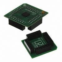
DEMO9S08JM16
Description
BOARD DEMO FOR JM16 FAMI
Manufacturer
Freescale Semiconductor
Type
MCUr
Datasheets
1.DEMO9S08JM16.pdf
(47 pages)
2.DEMO9S08JM16.pdf
(5 pages)
3.DEMO9S08JM16.pdf
(4 pages)
4.DEMO9S08JM16.pdf
(386 pages)
Specifications of DEMO9S08JM16
Contents
Board with Daughter card, Cable, Documentation, Mini-AB USB Kit
Processor To Be Evaluated
MC9S08JM16
Data Bus Width
8 bit
Interface Type
USB
Silicon Manufacturer
Freescale
Core Architecture
HCS08
Core Sub-architecture
HCS08
Silicon Core Number
MC9S08
Silicon Family Name
Flexis - S08JM
Rohs Compliant
Yes
For Use With/related Products
MC9S08JM16
Lead Free Status / RoHS Status
Lead free / RoHS Compliant


15.2.2
When the SPI is enabled as a master and SPI pin control zero (SPC0) is 0 (not bidirectional mode), this
pin is the serial data output. When the SPI is enabled as a slave and SPC0 = 0, this pin is the serial data
input. If SPC0 = 1 to select single-wire bidirectional mode, and master mode is selected, this pin becomes
the bidirectional data I/O pin (MOMI). Also, the bidirectional mode output enable bit determines whether
the pin acts as an input (BIDIROE = 0) or an output (BIDIROE = 1). If SPC0 = 1 and slave mode is
selected, this pin is not used by the SPI and reverts to being a general-purpose port I/O pin.
15.2.3
When the SPI is enabled as a master and SPI pin control zero (SPC0) is 0 (not bidirectional mode), this
pin is the serial data input. When the SPI is enabled as a slave and SPC0 = 0, this pin is the serial data
output. If SPC0 = 1 to select single-wire bidirectional mode, and slave mode is selected, this pin becomes
the bidirectional data I/O pin (SISO) and the bidirectional mode output enable bit determines whether the
pin acts as an input (BIDIROE = 0) or an output (BIDIROE = 1). If SPC0 = 1 and master mode is selected,
this pin is not used by the SPI and reverts to being a general-purpose port I/O pin.
15.2.4
When the SPI is enabled as a slave, this pin is the low-true slave select input. When the SPI is enabled as
a master and mode fault enable is off (MODFEN = 0), this pin is not used by the SPI and reverts to being
a general-purpose port I/O pin. When the SPI is enabled as a master and MODFEN = 1, the slave select
output enable bit determines whether this pin acts as the mode fault input (SSOE = 0) or as the slave select
output (SSOE = 1).
15.3
The SPI has eight 8-bit registers to select SPI options, control baud rate, report SPI status, hold an SPI data
match value, and for transmit/receive data.
Refer to the direct-page register summary in the Memory chapter of this data sheet for the absolute address
assignments for all SPI registers. This section refers to registers and control bits only by their names, and
a Freescale-provided equate or header file is used to translate these names into the appropriate absolute
addresses.
15.3.1
This read/write register includes the SPI enable control, interrupt enables, and configuration options.
Freescale Semiconductor
Reset
W
R
Register Definition
SPIE
MOSI — Master Data Out, Slave Data In
MISO — Master Data In, Slave Data Out
SS — Slave Select
SPI Control Register 1 (SPIxC1)
0
7
SPE
0
6
Figure 15-5. SPI Control Register 1 (SPIxC1)
MC9S08JM16 Series Data Sheet, Rev. 2
SPTIE
0
5
MSTR
0
4
CPOL
3
0
CPHA
Serial Peripheral Interface (S08SPI16V1)
1
2
SSOE
0
1
LSBFE
0
0
245
Related parts for DEMO9S08JM16
Image
Part Number
Description
Manufacturer
Datasheet
Request
R

Part Number:
Description:
Manufacturer:
Freescale Semiconductor, Inc
Datasheet:
Part Number:
Description:
Manufacturer:
Freescale Semiconductor, Inc
Datasheet:
Part Number:
Description:
Manufacturer:
Freescale Semiconductor, Inc
Datasheet:
Part Number:
Description:
Manufacturer:
Freescale Semiconductor, Inc
Datasheet:
Part Number:
Description:
Manufacturer:
Freescale Semiconductor, Inc
Datasheet:
Part Number:
Description:
Manufacturer:
Freescale Semiconductor, Inc
Datasheet:
Part Number:
Description:
Manufacturer:
Freescale Semiconductor, Inc
Datasheet:
Part Number:
Description:
Manufacturer:
Freescale Semiconductor, Inc
Datasheet:
Part Number:
Description:
Manufacturer:
Freescale Semiconductor, Inc
Datasheet:
Part Number:
Description:
Manufacturer:
Freescale Semiconductor, Inc
Datasheet:
Part Number:
Description:
Manufacturer:
Freescale Semiconductor, Inc
Datasheet:
Part Number:
Description:
Manufacturer:
Freescale Semiconductor, Inc
Datasheet:
Part Number:
Description:
Manufacturer:
Freescale Semiconductor, Inc
Datasheet:
Part Number:
Description:
Manufacturer:
Freescale Semiconductor, Inc
Datasheet:
Part Number:
Description:
Manufacturer:
Freescale Semiconductor, Inc
Datasheet: