DEMO9S08JM16 Freescale Semiconductor, DEMO9S08JM16 Datasheet - Page 229
DEMO9S08JM16
Manufacturer Part Number
DEMO9S08JM16
Description
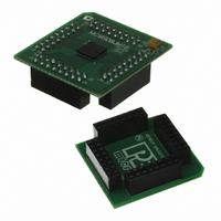
BOARD DEMO FOR JM16 FAMI
Manufacturer
Freescale Semiconductor
Type
MCUr
Datasheets
1.DEMO9S08JM16.pdf
(47 pages)
2.DEMO9S08JM16.pdf
(5 pages)
3.DEMO9S08JM16.pdf
(4 pages)
4.DEMO9S08JM16.pdf
(386 pages)
Specifications of DEMO9S08JM16
Contents
Board with Daughter card, Cable, Documentation, Mini-AB USB Kit
Processor To Be Evaluated
MC9S08JM16
Data Bus Width
8 bit
Interface Type
USB
Silicon Manufacturer
Freescale
Core Architecture
HCS08
Core Sub-architecture
HCS08
Silicon Core Number
MC9S08
Silicon Family Name
Flexis - S08JM
Rohs Compliant
Yes
For Use With/related Products
MC9S08JM16
Lead Free Status / RoHS Status
Lead free / RoHS Compliant


14.2.5
This register has one read-only status flag.
Freescale Semiconductor
RXEDGIF
Reset
LBKDIF
RXINV
RWUID
BRK13
Field
Field
FE
PF
1
0
7
6
4
3
2
W
R
1
LBKDIF
SCI Status Register 2 (SCIxS2)
Framing Error Flag — FE is set at the same time as RDRF when the receiver detects a logic 0 where the stop
bit was expected. This suggests the receiver was not properly aligned to a character frame. To clear FE, read
SCIxS1 with FE = 1 and then read the SCI data register (SCIxD).
0 No framing error detected. This does not guarantee the framing is correct.
1 Framing error.
Parity Error Flag — PF is set at the same time as RDRF when parity is enabled (PE = 1) and the parity bit in
the received character does not agree with the expected parity value. To clear PF, read SCIxS1 and then read
the SCI data register (SCIxD).
0 No parity error.
1 Parity error.
LIN Break Detect Interrupt Flag — LBKDIF is set when the LIN break detect circuitry is enabled and a LIN break
character is detected. LBKDIF is cleared by writing a “1” to it.
0 No LIN break character has been detected.
1 LIN break character has been detected.
RxD Pin Active Edge Interrupt Flag — RXEDGIF is set when an active edge (falling if RXINV = 0, rising if
RXINV=1) on the RxD pin occurs. RXEDGIF is cleared by writing a “1” to it.
0 No active edge on the receive pin has occurred.
1 An active edge on the receive pin has occurred.
Receive Data Inversion — Setting this bit reverses the polarity of the received data input.
0 Receive data not inverted
1 Receive data inverted
Receive Wake Up Idle Detect— RWUID controls whether the idle character that wakes up the receiver sets the
IDLE bit.
0 During receive standby state (RWU = 1), the IDLE bit does not get set upon detection of an idle character.
1 During receive standby state (RWU = 1), the IDLE bit gets set upon detection of an idle character.
Break Character Generation Length — BRK13 is used to select a longer transmitted break character length.
Detection of a framing error is not affected by the state of this bit.
0 Break character is transmitted with length of 10 bit times (11 if M = 1)
1 Break character is transmitted with length of 13 bit times (14 if M = 1)
0
7
= Unimplemented or Reserved
RXEDGIF
0
6
Table 14-5. SCIxS1 Field Descriptions (continued)
Figure 14-9. SCI Status Register 2 (SCIxS2)
Table 14-6. SCIxS2 Field Descriptions
MC9S08JM16 Series Data Sheet, Rev. 2
0
0
5
RXINV
0
4
Description
Description
RWUID
3
0
Serial Communications Interface (S08SCIV4)
BRK13
0
2
LBKDE
0
1
RAF
0
0
229
Related parts for DEMO9S08JM16
Image
Part Number
Description
Manufacturer
Datasheet
Request
R

Part Number:
Description:
Manufacturer:
Freescale Semiconductor, Inc
Datasheet:
Part Number:
Description:
Manufacturer:
Freescale Semiconductor, Inc
Datasheet:
Part Number:
Description:
Manufacturer:
Freescale Semiconductor, Inc
Datasheet:
Part Number:
Description:
Manufacturer:
Freescale Semiconductor, Inc
Datasheet:
Part Number:
Description:
Manufacturer:
Freescale Semiconductor, Inc
Datasheet:
Part Number:
Description:
Manufacturer:
Freescale Semiconductor, Inc
Datasheet:
Part Number:
Description:
Manufacturer:
Freescale Semiconductor, Inc
Datasheet:
Part Number:
Description:
Manufacturer:
Freescale Semiconductor, Inc
Datasheet:
Part Number:
Description:
Manufacturer:
Freescale Semiconductor, Inc
Datasheet:
Part Number:
Description:
Manufacturer:
Freescale Semiconductor, Inc
Datasheet:
Part Number:
Description:
Manufacturer:
Freescale Semiconductor, Inc
Datasheet:
Part Number:
Description:
Manufacturer:
Freescale Semiconductor, Inc
Datasheet:
Part Number:
Description:
Manufacturer:
Freescale Semiconductor, Inc
Datasheet:
Part Number:
Description:
Manufacturer:
Freescale Semiconductor, Inc
Datasheet:
Part Number:
Description:
Manufacturer:
Freescale Semiconductor, Inc
Datasheet: