DEMO9S08LC60 Freescale Semiconductor, DEMO9S08LC60 Datasheet - Page 64
DEMO9S08LC60
Manufacturer Part Number
DEMO9S08LC60
Description
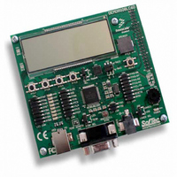
BOARD DEMO FOR 9S08LC60
Manufacturer
Freescale Semiconductor
Type
MCUr
Datasheets
1.DEMO9S08LC60.pdf
(360 pages)
2.DEMO9S08LC60.pdf
(32 pages)
3.DEMO9S08LC60.pdf
(2 pages)
Specifications of DEMO9S08LC60
Contents
Evaluation Board
Processor To Be Evaluated
MC9S08LC60
Interface Type
RS-232, USB
Silicon Manufacturer
Freescale
Core Architecture
HCS08
Core Sub-architecture
HCS08
Silicon Core Number
MC9S08
Silicon Family Name
S08LC
Rohs Compliant
Yes
For Use With/related Products
MC9S08LC60
Lead Free Status / RoHS Status
Lead free / RoHS Compliant


Chapter 5 Resets, Interrupts, and System Configuration
Each of these sources, with the exception of the background debug forced reset, has an associated bit in
the system reset status register. Whenever the MCU enters reset, the internal clock generator (ICG) module
switches to self-clocked mode with the frequency of f
internal bus cycles where the internal bus frequency is half the ICG frequency. After the 34 cycles are
completed, the pin is released and will be pulled up by the internal pullup resistor, unless it is held low
externally. After the pin is released, it is sampled after another 38 cycles to determine whether the reset pin
is the cause of the MCU reset.
5.4
The COP watchdog is intended to force a system reset when the application software fails to execute as
expected. To prevent a system reset from the COP timer (when it is enabled), application software must
reset the COP timer periodically. If the application program gets lost and fails to reset the COP before it
times out, a system reset is generated to force the system back to a known starting point.
After any reset, the COPE becomes set in SOPT1 enabling the COP watchdog (see
Options Register
it can be disabled by clearing COPE. The COP counter is reset by writing any value to the address of SRS.
This write does not affect the data in the read-only SRS. Instead, the act of writing to this address is
decoded and sends a reset signal to the COP counter.
The COPCLKS bit in SOPT2 (see
information) selects the clock source used for the COP timer. The clock source options are either the bus
clock or an internal 1kHz clock source. With each clock source, there is an associated short and long
time-out controlled by COPT in SOPT1.
COPT bits. The COP watchdog defaults to operation from the 1kHz clock source and the associated long
time-out (2
64
•
•
•
•
Illegal opcode detect
Background debug forced reset
External pin reset (PIN) — can be disabled using RSTPE in SOPT2
Clock generator loss of lock and loss of clock reset
Computer Operating Properly (COP) Watchdog
8
cycles).
1
Values are shown in this column based on t
Section A.10.1, “Control
(SOPT1),” for additional information). If the COP watchdog is not used in an application,
COPCLKS
0
0
1
1
Control Bits
MC9S08LC60 Series Data Sheet: Technical Data, Rev. 4
Table 5-1. COP Configuration Options
Section 5.8.5, “System Options Register
COPT
Timing,” for the tolerance of this value.
0
1
0
1
Table 5-1
Clock Source
summaries the control functions of the COPCLKS and
~1 kHz
~1 kHz
RTI
Bus
Bus
Self_reset
= 1 ms. See t
selected. The reset pin is driven low for 34
RTI
COP Overflow Count
2
2
8
in the appendix
5
cycles (256 ms)
cycles (32 ms)
2
2
13
18
cycles
cycles
(SOPT2),” for additional
Section 5.8.4, “System
1
1
Freescale Semiconductor
Related parts for DEMO9S08LC60
Image
Part Number
Description
Manufacturer
Datasheet
Request
R

Part Number:
Description:
Manufacturer:
Freescale Semiconductor, Inc
Datasheet:
Part Number:
Description:
Manufacturer:
Freescale Semiconductor, Inc
Datasheet:
Part Number:
Description:
Manufacturer:
Freescale Semiconductor, Inc
Datasheet:
Part Number:
Description:
Manufacturer:
Freescale Semiconductor, Inc
Datasheet:
Part Number:
Description:
Manufacturer:
Freescale Semiconductor, Inc
Datasheet:
Part Number:
Description:
Manufacturer:
Freescale Semiconductor, Inc
Datasheet:
Part Number:
Description:
Manufacturer:
Freescale Semiconductor, Inc
Datasheet:
Part Number:
Description:
Manufacturer:
Freescale Semiconductor, Inc
Datasheet:
Part Number:
Description:
Manufacturer:
Freescale Semiconductor, Inc
Datasheet:
Part Number:
Description:
Manufacturer:
Freescale Semiconductor, Inc
Datasheet:
Part Number:
Description:
Manufacturer:
Freescale Semiconductor, Inc
Datasheet:
Part Number:
Description:
Manufacturer:
Freescale Semiconductor, Inc
Datasheet:
Part Number:
Description:
Manufacturer:
Freescale Semiconductor, Inc
Datasheet:
Part Number:
Description:
Manufacturer:
Freescale Semiconductor, Inc
Datasheet:
Part Number:
Description:
Manufacturer:
Freescale Semiconductor, Inc
Datasheet: