DEMO9S08LC60 Freescale Semiconductor, DEMO9S08LC60 Datasheet - Page 277
DEMO9S08LC60
Manufacturer Part Number
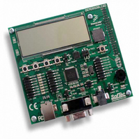
DEMO9S08LC60
Description
BOARD DEMO FOR 9S08LC60
Manufacturer
Freescale Semiconductor
Type
MCUr
Datasheets
1.DEMO9S08LC60.pdf
(360 pages)
2.DEMO9S08LC60.pdf
(32 pages)
3.DEMO9S08LC60.pdf
(2 pages)
Specifications of DEMO9S08LC60
Contents
Evaluation Board
Processor To Be Evaluated
MC9S08LC60
Interface Type
RS-232, USB
Silicon Manufacturer
Freescale
Core Architecture
HCS08
Core Sub-architecture
HCS08
Silicon Core Number
MC9S08
Silicon Family Name
S08LC
Rohs Compliant
Yes
For Use With/related Products
MC9S08LC60
Lead Free Status / RoHS Status
Lead free / RoHS Compliant


Freescale Semiconductor
ADLSMP
ADICLK
ADLPC
MODE
Field
ADIV
6:5
3:2
1:0
7
4
Reset:
W
R
Low Power Configuration — ADLPC controls the speed and power configuration of the successive
approximation converter. This is used to optimize power consumption when higher sample rates are not required.
0 High speed configuration
1 Low power configuration: {FC31}The power is reduced at the expense of maximum clock speed.
Clock Divide Select — ADIV select the divide ratio used by the ADC to generate the internal clock ADCK.
Table 15-6
Long Sample Time Configuration — ADLSMP selects between long and short sample time. This adjusts the
sample period to allow higher impedance inputs to be accurately sampled or to maximize conversion speed for
lower impedance inputs. Longer sample times can also be used to lower overall power consumption when
continuous conversions are enabled if high conversion rates are not required.
0 Short sample time
1 Long sample time
Conversion Mode Selection — MODE bits are used to select between 12-, 10- or 8-bit operation. See
Table
Input Clock Select — ADICLK bits select the input clock source to generate the internal clock ADCK. See
Table
ADLPC
15-7.
15-8.
7
0
shows the available clock configurations.
MODE
ADIV
00
01
10
11
00
01
10
11
MC9S08LC60 Series Data Sheet: Technical Data, Rev. 4
Table 15-5. ADCCFG Register Field Descriptions
0
Figure 15-10. Configuration Register (ADCCFG)
6
ADIV
8-bit conversion (N=8)
12-bit conversion (N=12)
10-bit conversion (N=10)
Reserved
Table 15-6. Clock Divide Select
Table 15-7. Conversion Modes
0
5
Divide Ratio
1
2
4
8
ADLSMP
0
4
Mode Description
Description
Chapter 15 Analog-to-Digital Converter (S08ADC12V1)
0
3
MODE
Input clock ÷ 2
Input clock ÷ 4
Input clock ÷ 8
Clock Rate
Input clock
0
2
0
1
ADICLK
0
0
277
Related parts for DEMO9S08LC60
Image
Part Number
Description
Manufacturer
Datasheet
Request
R

Part Number:
Description:
Manufacturer:
Freescale Semiconductor, Inc
Datasheet:
Part Number:
Description:
Manufacturer:
Freescale Semiconductor, Inc
Datasheet:
Part Number:
Description:
Manufacturer:
Freescale Semiconductor, Inc
Datasheet:
Part Number:
Description:
Manufacturer:
Freescale Semiconductor, Inc
Datasheet:
Part Number:
Description:
Manufacturer:
Freescale Semiconductor, Inc
Datasheet:
Part Number:
Description:
Manufacturer:
Freescale Semiconductor, Inc
Datasheet:
Part Number:
Description:
Manufacturer:
Freescale Semiconductor, Inc
Datasheet:
Part Number:
Description:
Manufacturer:
Freescale Semiconductor, Inc
Datasheet:
Part Number:
Description:
Manufacturer:
Freescale Semiconductor, Inc
Datasheet:
Part Number:
Description:
Manufacturer:
Freescale Semiconductor, Inc
Datasheet:
Part Number:
Description:
Manufacturer:
Freescale Semiconductor, Inc
Datasheet:
Part Number:
Description:
Manufacturer:
Freescale Semiconductor, Inc
Datasheet:
Part Number:
Description:
Manufacturer:
Freescale Semiconductor, Inc
Datasheet:
Part Number:
Description:
Manufacturer:
Freescale Semiconductor, Inc
Datasheet:
Part Number:
Description:
Manufacturer:
Freescale Semiconductor, Inc
Datasheet: