DEMO9S08LC60 Freescale Semiconductor, DEMO9S08LC60 Datasheet - Page 205
DEMO9S08LC60
Manufacturer Part Number
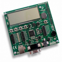
DEMO9S08LC60
Description
BOARD DEMO FOR 9S08LC60
Manufacturer
Freescale Semiconductor
Type
MCUr
Datasheets
1.DEMO9S08LC60.pdf
(360 pages)
2.DEMO9S08LC60.pdf
(32 pages)
3.DEMO9S08LC60.pdf
(2 pages)
Specifications of DEMO9S08LC60
Contents
Evaluation Board
Processor To Be Evaluated
MC9S08LC60
Interface Type
RS-232, USB
Silicon Manufacturer
Freescale
Core Architecture
HCS08
Core Sub-architecture
HCS08
Silicon Core Number
MC9S08
Silicon Family Name
S08LC
Rohs Compliant
Yes
For Use With/related Products
MC9S08LC60
Lead Free Status / RoHS Status
Lead free / RoHS Compliant


11.3.4
TPMxCnSC contains the channel interrupt status flag and control bits that are used to configure the
interrupt enable, channel configuration, and pin function.
Freescale Semiconductor
ELSn[B:A]
Reset
CHnIE
CHnF
MSnB
MSnA
Field
3:2
7
6
5
4
W
R
CHnF
Timer x Channel n Status and Control Register (TPMxCnSC)
Channel n Flag — When channel n is configured for input capture, this flag bit is set when an active edge occurs
on the channel n pin. When channel n is an output compare or edge-aligned PWM channel, CHnF is set when
the value in the TPM counter registers matches the value in the TPM channel n value registers. This flag is
seldom used with center-aligned PWMs because it is set every time the counter matches the channel value
register, which correspond to both edges of the active duty cycle period.
A corresponding interrupt is requested when CHnF is set and interrupts are enabled (CHnIE = 1). Clear CHnF
by reading TPMxCnSC while CHnF is set and then writing a 0 to CHnF. If another interrupt request occurs before
the clearing sequence is complete, the sequence is reset so CHnF would remain set after the clear sequence
was completed for the earlier CHnF. This is done so a CHnF interrupt request cannot be lost by clearing a
previous CHnF. Reset clears CHnF. Writing a 1 to CHnF has no effect.
0 No input capture or output compare event occurred on channel n
1 Input capture or output compare event occurred on channel n
Channel n Interrupt Enable — This read/write bit enables interrupts from channel n. Reset clears CHnIE.
0 Channel n interrupt requests disabled (use software polling)
1 Channel n interrupt requests enabled
Mode Select B for TPM Channel n — When CPWMS = 0, MSnB = 1 configures TPM channel n for
edge-aligned PWM mode. For a summary of channel mode and setup controls, refer to
Mode Select A for TPM Channel n — When CPWMS = 0 and MSnB = 0, MSnA configures TPM channel n for
input capture mode or output compare mode. Refer to
controls.
Edge/Level Select Bits — Depending on the operating mode for the timer channel as set by
CPWMS:MSnB:MSnA and shown in
input capture event, select the level that will be driven in response to an output compare match, or select the
polarity of the PWM output.
Setting ELSnB:ELSnA to 0:0 configures the related timer pin as a general-purpose I/O pin unrelated to any timer
channel functions. This function is typically used to temporarily disable an input capture channel or to make the
timer pin available as a general-purpose I/O pin when the associated timer channel is set up as a software timer
that does not require the use of a pin.
0
7
Figure 11-8. Timer x Channel n Status and Control Register (TPMxCnSC)
= Unimplemented or Reserved
CHnIE
0
6
Table 11-4. TPMxCnSC Register Field Descriptions
MC9S08LC60 Series Data Sheet: Technical Data, Rev. 4
MSnB
0
5
Table
MSnA
11-5, these bits select the polarity of the input edge that triggers an
0
4
Description
Table 11-5
ELSnB
3
0
Chapter 11 Timer/Pulse-Width Modulator (S08TPMV2)
for a summary of channel mode and setup
ELSnA
0
2
Table
0
0
1
11-5.
0
0
0
205
Related parts for DEMO9S08LC60
Image
Part Number
Description
Manufacturer
Datasheet
Request
R

Part Number:
Description:
Manufacturer:
Freescale Semiconductor, Inc
Datasheet:
Part Number:
Description:
Manufacturer:
Freescale Semiconductor, Inc
Datasheet:
Part Number:
Description:
Manufacturer:
Freescale Semiconductor, Inc
Datasheet:
Part Number:
Description:
Manufacturer:
Freescale Semiconductor, Inc
Datasheet:
Part Number:
Description:
Manufacturer:
Freescale Semiconductor, Inc
Datasheet:
Part Number:
Description:
Manufacturer:
Freescale Semiconductor, Inc
Datasheet:
Part Number:
Description:
Manufacturer:
Freescale Semiconductor, Inc
Datasheet:
Part Number:
Description:
Manufacturer:
Freescale Semiconductor, Inc
Datasheet:
Part Number:
Description:
Manufacturer:
Freescale Semiconductor, Inc
Datasheet:
Part Number:
Description:
Manufacturer:
Freescale Semiconductor, Inc
Datasheet:
Part Number:
Description:
Manufacturer:
Freescale Semiconductor, Inc
Datasheet:
Part Number:
Description:
Manufacturer:
Freescale Semiconductor, Inc
Datasheet:
Part Number:
Description:
Manufacturer:
Freescale Semiconductor, Inc
Datasheet:
Part Number:
Description:
Manufacturer:
Freescale Semiconductor, Inc
Datasheet:
Part Number:
Description:
Manufacturer:
Freescale Semiconductor, Inc
Datasheet: