DEMO9S08LC60 Freescale Semiconductor, DEMO9S08LC60 Datasheet - Page 273
DEMO9S08LC60
Manufacturer Part Number
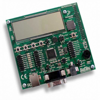
DEMO9S08LC60
Description
BOARD DEMO FOR 9S08LC60
Manufacturer
Freescale Semiconductor
Type
MCUr
Datasheets
1.DEMO9S08LC60.pdf
(360 pages)
2.DEMO9S08LC60.pdf
(32 pages)
3.DEMO9S08LC60.pdf
(2 pages)
Specifications of DEMO9S08LC60
Contents
Evaluation Board
Processor To Be Evaluated
MC9S08LC60
Interface Type
RS-232, USB
Silicon Manufacturer
Freescale
Core Architecture
HCS08
Core Sub-architecture
HCS08
Silicon Core Number
MC9S08
Silicon Family Name
S08LC
Rohs Compliant
Yes
For Use With/related Products
MC9S08LC60
Lead Free Status / RoHS Status
Lead free / RoHS Compliant


Freescale Semiconductor
COCO
ADCO
ADCH
Field
AIEN
4:0
7
6
5
Reset:
W
R
Conversion Complete Flag — The COCO flag is a read-only bit which is set each time a conversion is
completed when the compare function is disabled (ACFE = 0). When the compare function is enabled (ACFE =
1) the COCO flag is set upon completion of a conversion only if the compare result is true. This bit is cleared
whenever ADCSC1 is written or whenever ADCRL is read.
0 Conversion not completed
1 Conversion completed
Interrupt Enable — AIEN is used to enable conversion complete interrupts. When COCO becomes set while
AIEN is high, an interrupt is asserted.
0 Conversion complete interrupt disabled
1 Conversion complete interrupt enabled
Continuous Conversion Enable — ADCO is used to enable continuous conversions.
0 One conversion following a write to the ADCSC1 when software triggered operation is selected, or one
1 Continuous conversions initiated following a write to ADCSC1 when software triggered operation is selected.
Input Channel Select — The ADCH bits form a 5-bit field which is used to select one of the input channels. The
input channels are detailed in
The successive approximation converter subsystem is turned off when the channel select bits are all set to 1.
This feature allows for explicit disabling of the ADC and isolation of the input channel from all sources.
Terminating continuous conversions this way will prevent an additional, single conversion from being performed.
It is not necessary to set the channel select bits to all 1s to place the ADC in a low-power state when continuous
conversions are not enabled because the module automatically enters a low-power state when a conversion
completes.
conversion following assertion of ADHWT when hardware triggered operation is selected.
Continuous conversions are initiated by an ADHWT event when hardware triggered operation is selected.
COCO
7
0
ADCH
00000
00001
00010
00011
00100
00101
00110
00111
= Unimplemented or Reserved
Figure 15-3. Status and Control Register (ADCSC1)
AIEN
MC9S08LC60 Series Data Sheet: Technical Data, Rev. 4
Table 15-3. ADCSC1 Register Field Descriptions
0
6
Figure 15-4. Input Channel Select
ADCO
Figure
Input Select
0
5
AD0
AD1
AD2
AD3
AD4
AD5
AD6
AD7
15-4.
1
4
Description
Chapter 15 Analog-to-Digital Converter (S08ADC12V1)
1
3
ADCH
ADCH
10000
10001
10010
10011
10100
10101
10110
10111
1
2
1
1
Input Select
AD16
AD17
AD18
AD19
AD20
AD21
AD22
AD23
1
0
273
Related parts for DEMO9S08LC60
Image
Part Number
Description
Manufacturer
Datasheet
Request
R

Part Number:
Description:
Manufacturer:
Freescale Semiconductor, Inc
Datasheet:
Part Number:
Description:
Manufacturer:
Freescale Semiconductor, Inc
Datasheet:
Part Number:
Description:
Manufacturer:
Freescale Semiconductor, Inc
Datasheet:
Part Number:
Description:
Manufacturer:
Freescale Semiconductor, Inc
Datasheet:
Part Number:
Description:
Manufacturer:
Freescale Semiconductor, Inc
Datasheet:
Part Number:
Description:
Manufacturer:
Freescale Semiconductor, Inc
Datasheet:
Part Number:
Description:
Manufacturer:
Freescale Semiconductor, Inc
Datasheet:
Part Number:
Description:
Manufacturer:
Freescale Semiconductor, Inc
Datasheet:
Part Number:
Description:
Manufacturer:
Freescale Semiconductor, Inc
Datasheet:
Part Number:
Description:
Manufacturer:
Freescale Semiconductor, Inc
Datasheet:
Part Number:
Description:
Manufacturer:
Freescale Semiconductor, Inc
Datasheet:
Part Number:
Description:
Manufacturer:
Freescale Semiconductor, Inc
Datasheet:
Part Number:
Description:
Manufacturer:
Freescale Semiconductor, Inc
Datasheet:
Part Number:
Description:
Manufacturer:
Freescale Semiconductor, Inc
Datasheet:
Part Number:
Description:
Manufacturer:
Freescale Semiconductor, Inc
Datasheet: