PCM18XT0 Microchip Technology, PCM18XT0 Datasheet - Page 479
PCM18XT0
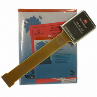
Manufacturer Part Number
PCM18XT0
Description
MODULE PROC PIC18F4685
Manufacturer
Microchip Technology
Datasheet
1.PCM18XT0.pdf
(484 pages)
Specifications of PCM18XT0
Accessory Type
Processor Module
Product
Microcontroller Modules
Core Processor
PIC18F4685
Lead Free Status / RoHS Status
Not applicable / Not applicable
For Use With/related Products
ICE2000
For Use With
ICE2000 - EMULATOR MPLAB-ICE 2000 POD
Lead Free Status / RoHS Status
Lead free / RoHS Compliant, Not applicable / Not applicable


Timing Diagrams and Specifications ................................ 437
© 2009 Microchip Technology Inc.
SPI Mode (Slave Mode with CKE = 0) ..................... 196
SPI Mode (Slave Mode with CKE = 1) ..................... 196
Stop Condition Receive or Transmit Mode .............. 222
Synchronous Reception (Master Mode, SREN) ...... 246
Synchronous Transmission ...................................... 244
Synchronous Transmission
Time-out Sequence on POR w/PLL Enabled
Time-out Sequence on Power-up
Time-out Sequence on Power-up
Time-out Sequence on Power-up
Timer0 and Timer1 External Clock .......................... 441
Transition for Entry to Idle Mode ................................ 40
Transition for Entry to SEC_RUN Mode .................... 37
Transition for Entry to Sleep Mode ............................ 39
Transition for Two-Speed Start-up
Transition for Wake From Idle to Run Mode .............. 40
Transition for Wake From Sleep (HSPLL) ................. 39
Transition From RC_RUN Mode
Transition From SEC_RUN Mode
Transition to RC_RUN Mode ..................................... 38
AC Characteristics
Capture/Compare/PWM Requirements
CLKO and I/O Requirements ................................... 439
EUSART Synchronous Receive Requirements ....... 452
EUSART Synchronous Transmission
Example SPI Mode Requirements
Example SPI Mode Requirements
Example SPI Mode Requirements
(Through TXEN) .............................................. 245
(MCLR Tied to V
(MCLR Not Tied to V
(MCLR Tied to V
(INTOSC to HSPLL) ........................................ 357
to PRI_RUN Mode ............................................. 38
to PRI_RUN Mode (HSPLL) .............................. 37
Internal RC Accuracy ....................................... 438
(All CCP Modules) ........................................... 442
(Master Mode, CKE = 0) .................................. 444
(Master Mode, CKE = 1) .................................. 445
(Slave Mode, CKE = 0) .................................... 446
(MCLR Not Tied to V
Requirements ................................................. 452
DD
DD
) ........................................... 49
, V
DD
DD
DD
), Case 1 ....................... 48
), Case 2 ...................... 48
Rise Tpwrt) ................ 48
PIC18F2682/2685/4682/4685
Top-of-Stack Access .......................................................... 64
TRISE Register
TSTFSZ ........................................................................... 405
Two-Speed Start-up ................................................. 345, 357
Two-Word Instructions
TXSTA Register
V
Voltage Reference Specifications .................................... 433
W
Watchdog Timer (WDT) ........................................... 345, 355
WCOL ...................................................... 217, 218, 219, 222
WCOL Status Flag ................................... 217, 218, 219, 222
WWW Address ................................................................ 481
WWW, On-Line Support ...................................................... 7
X
XORLW ........................................................................... 405
XORWF ........................................................................... 406
Example SPI Mode Requirements
External Clock Requirements .................................. 437
I
I
Master SSP I
Master SSP I
Parallel Slave Port Requirements
PLL Clock ................................................................ 438
Reset, Watchdog Timer, Oscillator Start-up
Timer0 and Timer1 External
PSPMODE Bit ......................................................... 140
Example Cases ......................................................... 68
BRGH Bit ................................................................. 233
Associated Registers ............................................... 356
Control Register ....................................................... 355
Programming Considerations .................................. 355
2
2
C Bus Data Requirements (Slave Mode) .............. 449
C Bus Start/Stop Bits Requirements
(Slave Mode, CKE = 1) .................................... 447
(Slave Mode) ................................................... 448
(PIC18F4682/4685) ......................................... 443
Timer, Power-up Timer and Brown-out
Reset Requirements ........................................ 440
Clock Requirements ........................................ 441
2
2
C Bus Data Requirements ................ 451
C Bus Start/Stop Bits Requirements . 450
DS39761C-page 479
Related parts for PCM18XT0
Image
Part Number
Description
Manufacturer
Datasheet
Request
R

Part Number:
Description:
Manufacturer:
Microchip Technology Inc.
Datasheet:
Part Number:
Description:
Manufacturer:
Microchip Technology Inc.
Datasheet:
Part Number:
Description:
Manufacturer:
Microchip Technology Inc.
Datasheet:
Part Number:
Description:
Manufacturer:
Microchip Technology Inc.
Datasheet:
Part Number:
Description:
Manufacturer:
Microchip Technology Inc.
Datasheet:
Part Number:
Description:
Manufacturer:
Microchip Technology Inc.
Datasheet:
Part Number:
Description:
Manufacturer:
Microchip Technology Inc.
Datasheet:
Part Number:
Description:
Manufacturer:
Microchip Technology Inc.
Datasheet: