PCM18XT0 Microchip Technology, PCM18XT0 Datasheet - Page 317
PCM18XT0
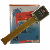
Manufacturer Part Number
PCM18XT0
Description
MODULE PROC PIC18F4685
Manufacturer
Microchip Technology
Datasheet
1.PCM18XT0.pdf
(484 pages)
Specifications of PCM18XT0
Accessory Type
Processor Module
Product
Microcontroller Modules
Core Processor
PIC18F4685
Lead Free Status / RoHS Status
Not applicable / Not applicable
For Use With/related Products
ICE2000
For Use With
ICE2000 - EMULATOR MPLAB-ICE 2000 POD
Lead Free Status / RoHS Status
Lead free / RoHS Compliant, Not applicable / Not applicable


23.2.5
This register controls the operation of the CAN module’s
I/O pins in relation to the rest of the microcontroller.
REGISTER 23-55: CIOCON: CAN I/O CONTROL REGISTER
© 2009 Microchip Technology Inc.
bit 7
Legend:
R = Readable bit
-n = Value at POR
bit 7-6
bit 5
bit 4
bit 3-0
Note 1:
U-0
—
CAN MODULE I/O CONTROL
Always set this bit when using differential bus to avoid signal crosstalk in CANTX from other nearby pins.
REGISTER
Unimplemented: Read as ‘0’
ENDRHI: Enable Drive High bit
1 = CANTX pin will drive V
0 = CANTX pin will be tri-state when recessive
CANCAP: CAN Message Receive Capture Enable bit
1 = Enable CAN capture, CAN message receive signal replaces input on RC2/CCP1
0 = Disable CAN capture, RC2/CCP1 input to CCP1 module
Unimplemented: Read as ‘0’
U-0
—
W = Writable bit
‘1’ = Bit is set
ENDRHI
R/W-0
(1)
DD
PIC18F2682/2685/4682/4685
when recessive
CANCAP
(1)
R/W-0
U = Unimplemented bit, read as ‘0’
‘0’ = Bit is cleared
U-0
—
U-0
—
x = Bit is unknown
U-0
—
DS39761C-page 317
U-0
—
bit 0
Related parts for PCM18XT0
Image
Part Number
Description
Manufacturer
Datasheet
Request
R

Part Number:
Description:
Manufacturer:
Microchip Technology Inc.
Datasheet:
Part Number:
Description:
Manufacturer:
Microchip Technology Inc.
Datasheet:
Part Number:
Description:
Manufacturer:
Microchip Technology Inc.
Datasheet:
Part Number:
Description:
Manufacturer:
Microchip Technology Inc.
Datasheet:
Part Number:
Description:
Manufacturer:
Microchip Technology Inc.
Datasheet:
Part Number:
Description:
Manufacturer:
Microchip Technology Inc.
Datasheet:
Part Number:
Description:
Manufacturer:
Microchip Technology Inc.
Datasheet:
Part Number:
Description:
Manufacturer:
Microchip Technology Inc.
Datasheet: