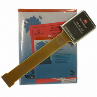
PCM18XT0 Microchip Technology, PCM18XT0 Datasheet - Page 440

PCM18XT0
Manufacturer Part Number
PCM18XT0
Description
MODULE PROC PIC18F4685
Manufacturer
Microchip Technology
Datasheet
1.PCM18XT0.pdf
(484 pages)
Specifications of PCM18XT0
Accessory Type
Processor Module
Product
Microcontroller Modules
Core Processor
PIC18F4685
Lead Free Status / RoHS Status
Not applicable / Not applicable
For Use With/related Products
ICE2000
For Use With
ICE2000 - EMULATOR MPLAB-ICE 2000 POD
Lead Free Status / RoHS Status
Lead free / RoHS Compliant, Not applicable / Not applicable
- Current page: 440 of 484
- Download datasheet (9Mb)
PIC18F2682/2685/4682/4685
FIGURE 27-7:
FIGURE 27-8:
TABLE 27-10: RESET, WATCHDOG TIMER, OSCILLATOR START-UP TIMER, POWER-UP TIMER
DS39761C-page 440
30
31
32
33
34
35
36
37
38
39
Param.
No.
Reference Voltage
Internal Reference
Watchdog
Note:
Time-out
Time-out
Enable Internal
I/O pins
Internal
Internal
Voltage Stable
PWRT
MCLR
Reset
Reset
Timer
T
T
T
T
T
T
T
T
T
T
POR
OSC
V
OST
CSD
MC
WDT
PWRT
IOZ
BOR
IRVST
LVD
IOBST
Sym
DD
L
V
Refer to Figure 27-4 for load conditions.
IRVST
V
DD
MCLR Pulse Width (low)
Watchdog Timer Time-out Period (no
postscaler)
Oscillation Start-up Timer Period
Power-up Timer Period
I/O High-Impedance from MCLR Low
or Watchdog Timer Reset
Brown-out Reset Pulse Width
Time for Internal Reference Voltage to
become stable
High/Low-Voltage Detect Pulse Width
CPU Start-up Time
Time for INTOSC to stabilize
AND BROWN-OUT RESET REQUIREMENTS
RESET, WATCHDOG TIMER, OSCILLATOR START-UP TIMER AND
POWER-UP TIMER TIMING
BROWN-OUT RESET TIMING
33
Characteristic
32
36
BV
DD
1024 T
55.6
Min
200
200
3.4
—
—
—
—
2
OSC
34
4.00
65.5
Typ
20
10
30
—
—
—
—
2
1
35
1024 T
Max
4.6
75
50
—
—
—
—
—
—
OSC
31
Units
© 2009 Microchip Technology Inc.
ms
ms
μs
μs
μs
μs
μs
μs
μs
—
T
V
V
OSC
DD
DD
≤ B
≤ V
= OSC1 period
34
Conditions
VDD
LVD
V
BGAP
(see D005)
= 1.2V
Related parts for PCM18XT0
Image
Part Number
Description
Manufacturer
Datasheet
Request
R

Part Number:
Description:
Manufacturer:
Microchip Technology Inc.
Datasheet:

Part Number:
Description:
Manufacturer:
Microchip Technology Inc.
Datasheet:

Part Number:
Description:
Manufacturer:
Microchip Technology Inc.
Datasheet:

Part Number:
Description:
Manufacturer:
Microchip Technology Inc.
Datasheet:

Part Number:
Description:
Manufacturer:
Microchip Technology Inc.
Datasheet:

Part Number:
Description:
Manufacturer:
Microchip Technology Inc.
Datasheet:

Part Number:
Description:
Manufacturer:
Microchip Technology Inc.
Datasheet:

Part Number:
Description:
Manufacturer:
Microchip Technology Inc.
Datasheet:


