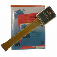
PCM18XT0 Microchip Technology, PCM18XT0 Datasheet - Page 23

PCM18XT0
Manufacturer Part Number
PCM18XT0
Description
MODULE PROC PIC18F4685
Manufacturer
Microchip Technology
Datasheet
1.PCM18XT0.pdf
(484 pages)
Specifications of PCM18XT0
Accessory Type
Processor Module
Product
Microcontroller Modules
Core Processor
PIC18F4685
Lead Free Status / RoHS Status
Not applicable / Not applicable
For Use With/related Products
ICE2000
For Use With
ICE2000 - EMULATOR MPLAB-ICE 2000 POD
Lead Free Status / RoHS Status
Lead free / RoHS Compliant, Not applicable / Not applicable
- Current page: 23 of 484
- Download datasheet (9Mb)
TABLE 1-3:
© 2009 Microchip Technology Inc.
RE0/RD/AN5
RE1/WR/AN6/C1OUT
RE2/CS/AN7/C2OUT
RE3
V
V
NC
Legend: TTL = TTL compatible input
SS
DD
RE0
RD
AN5
RE1
WR
AN6
C1OUT
RE2
CS
AN7
C2OUT
Pin Name
ST = Schmitt Trigger input with CMOS levels
O
= Output
PIC18F4682/4685 PINOUT I/O DESCRIPTIONS (CONTINUED)
11, 32
PDIP
12,
10
—
31
—
8
9
Pin Number
28, 29
6, 30,
QFN
7, 8,
25
26
27
31
13
—
12, 13,
TQFP
33, 34
6, 29
7, 28
25
26
27
—
PIC18F2682/2685/4682/4685
Type
Pin
I/O
I/O
I/O
—
—
O
O
P
P
I
I
I
I
I
I
Analog
Analog
Analog
Buffer
Type
TTL
TTL
TTL
TTL
TTL
ST
ST
ST
—
—
—
—
PORTE is a bidirectional I/O port.
See MCLR/V
Ground reference for logic and I/O pins.
Positive supply for logic and I/O pins.
No connect.
CMOS = CMOS compatible input or output
I
P
Digital I/O.
Read control for Parallel Slave Port
(see also WR and CS pins).
Analog input 5.
Digital I/O.
Write control for Parallel Slave Port
(see CS and RD pins).
Analog input 6.
Comparator 1 output.
Digital I/O.
Chip select control for Parallel Slave Port
(see related RD and WR pins).
Analog input 7.
Comparator 2 output.
= Power
= Input
PP
/RE3 pin.
Description
DS39761C-page 23
Related parts for PCM18XT0
Image
Part Number
Description
Manufacturer
Datasheet
Request
R

Part Number:
Description:
Manufacturer:
Microchip Technology Inc.
Datasheet:

Part Number:
Description:
Manufacturer:
Microchip Technology Inc.
Datasheet:

Part Number:
Description:
Manufacturer:
Microchip Technology Inc.
Datasheet:

Part Number:
Description:
Manufacturer:
Microchip Technology Inc.
Datasheet:

Part Number:
Description:
Manufacturer:
Microchip Technology Inc.
Datasheet:

Part Number:
Description:
Manufacturer:
Microchip Technology Inc.
Datasheet:

Part Number:
Description:
Manufacturer:
Microchip Technology Inc.
Datasheet:

Part Number:
Description:
Manufacturer:
Microchip Technology Inc.
Datasheet:


