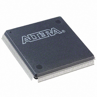
EP3C16Q240C8N Altera, EP3C16Q240C8N Datasheet - Page 243

EP3C16Q240C8N
Manufacturer Part Number
EP3C16Q240C8N
Description
IC CYCLONE III FPGA 16K 240PQFP
Manufacturer
Altera
Series
Cyclone® IIIr
Datasheets
1.EP3C5F256C8N.pdf
(5 pages)
2.EP3C5F256C8N.pdf
(34 pages)
3.EP3C5F256C8N.pdf
(66 pages)
4.EP3C5F256C8N.pdf
(14 pages)
5.EP3C5F256C8N.pdf
(76 pages)
6.EP3C16Q240C8N.pdf
(274 pages)
Specifications of EP3C16Q240C8N
Number Of Logic Elements/cells
15408
Number Of Labs/clbs
963
Total Ram Bits
516096
Number Of I /o
160
Voltage - Supply
1.15 V ~ 1.25 V
Mounting Type
Surface Mount
Operating Temperature
0°C ~ 85°C
Package / Case
240-MQFP, 240-PQFP
Family Name
Cyclone III
Number Of Logic Blocks/elements
15408
# I/os (max)
92
Frequency (max)
402MHz
Process Technology
65nm
Operating Supply Voltage (typ)
1.2V
Logic Cells
15408
Ram Bits
516096
Operating Supply Voltage (min)
1.15V
Operating Supply Voltage (max)
1.25V
Operating Temp Range
0C to 85C
Operating Temperature Classification
Commercial
Mounting
Surface Mount
Pin Count
240
Package Type
PQFP
For Use With
544-2601 - KIT DEV CYCLONE III LS EP3CLS200P0037 - BOARD DEV/EDUCATION ALTERA DE0544-2411 - KIT DEV NIOS II CYCLONE III ED.
Lead Free Status / RoHS Status
Lead free / RoHS Compliant
Number Of Gates
-
Lead Free Status / Rohs Status
Compliant
Other names
544-2458
Available stocks
Company
Part Number
Manufacturer
Quantity
Price
Company:
Part Number:
EP3C16Q240C8N
Manufacturer:
ALTERA64
Quantity:
74
Chapter 9: Configuration, Design Security, and Remote System Upgrades in the Cyclone III Device Family
Remote System Upgrade
Table 9–26. Remote System Upgrade Registers
© December 2009
Shift register
Control register
Update register
Status register
Register
Altera Corporation
This register is accessible by the logic array and allows the update, status, and control registers to be
written and sampled by user logic. Write access is enabled in remote update mode for factory
configurations to allow writes to the update register. Write access is disabled for all application
configurations in remote update mode.
This register contains the current configuration address, the user watchdog timer settings, one option
bit for checking early CONF_DONE, and one option bit for selecting the internal oscillator as the startup
state machine clock. During a read operation in an application configuration, this register is read into the
shift register. When a reconfiguration cycle is started, the contents of the update register are written into
the control register.
This register contains data similar to that in the control register. However, it can only be updated by the
factory configuration by shifting data into the shift register and issuing an update operation. When a
reconfiguration cycle is triggered by the factory configuration, the control register is updated with the
contents of the update register. During a read in a factory configuration, this register is read into the shift
register.
This register is written to by the remote system upgrade circuitry on every reconfiguration to record the
cause of the reconfiguration. This information is used by the factory configuration to determine the
appropriate action following a reconfiguration. During a capture cycle, this register is read into the shift
register.
Remote System Upgrade Registers
The remote system upgrade block contains a series of registers that stores the
configuration addresses, watchdog timer settings, and status information. These
registers are listed in
The control and status registers of the remote system upgrade are clocked by the
10-MHz internal oscillator (the same oscillator that controls the user watchdog timer).
However, the shift and update registers of the remote system upgrade are clocked by
the maximum frequency of 40-MHz user clock input (RU_CLK). There is no minimum
frequency for RU_CLK.
Remote System Upgrade Control Register
The remote system upgrade control register stores the application configuration
address, the user watchdog timer settings, and option bits for application
configuration. In remote update mode for the AS configuration scheme, the control
register address bits are set to all zeros (24'b0) at power up to load the AS factory
configuration. In remote update mode for the AP configuration scheme, the control
register address bits are set to 24'h010000 (24'b1 0000 0000 0000 0000) at power up to
load the AP default factory configuration. However, for the AP configuration scheme,
you can change the default factory configuration address to any desired address using
the APFC_BOOT_ADDR JTAG instruction. Additionally, a factory configuration in
remote update mode has write access to this register.
The control register bit positions are shown in
the figure, the numbers show the bit position of a setting in a register. For example, bit
number 35 is the enable bit for the watchdog timer.
Table
9–26.
Description
Figure 9–36
Cyclone III Device Handbook, Volume 1
and listed in
Table
9–27. In
9–83


