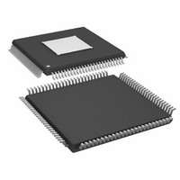
ADAU1445YSVZ-3A-RL Analog Devices Inc, ADAU1445YSVZ-3A-RL Datasheet - Page 64

ADAU1445YSVZ-3A-RL
Manufacturer Part Number
ADAU1445YSVZ-3A-RL
Description
175MHZ SigmaDSP,2x8 SRCs
Manufacturer
Analog Devices Inc
Series
SigmaDSP®r
Type
Audio Processorr
Specifications of ADAU1445YSVZ-3A-RL
Applications
Automotive Audio
Mounting Type
Surface Mount
Package / Case
100-TQFP Exposed Pad, 100-eTQFP, 100-HTQFP, 100-VQFP
Format
Fixed Point
Program Memory Size
Not RequiredKB
Operating Supply Voltage (typ)
1.8/3.3V
Operating Temp Range
-40C to 105C
Operating Temperature Classification
Industrial
Mounting
Surface Mount
Pin Count
100
Lead Free Status / RoHS Status
Lead free / RoHS Compliant
Lead Free Status / RoHS Status
Lead free / RoHS Compliant
Available stocks
Company
Part Number
Manufacturer
Quantity
Price
Company:
Part Number:
ADAU1445YSVZ-3A-RL
Manufacturer:
Analog Devices Inc
Quantity:
10 000
ADAU1445/ADAU1446
S/PDIF MODES AND SETTINGS
Table 52. Addresses of S/PDIF Modes Registers
Decimal
57536
57537
57538
57539
57540
57541
57542
57543
57544
57545
57546
57547
57548
S/PDIF Receiver—Read Auxiliary Output Register
(Address 0xE0C0)
Table 53. Bit Descriptions of Register 0xE0C0
Bit Position
[15]
[14]
[13]
[12]
[11:8]
[7:6]
[5:0]
This is a read-only register. It allows the S/PDIF auxiliary
output (including channel status, user data, and validity bit)
to be read.
Address
Hex
E0C0
E0C1
E0C2
E0C3
E0C4
E0C5
E0C6
E0C7
E0C8
E0C9
E0CA
E0CB
E0CC
Name
S/PDIF receiver—read
auxiliary output
S/PDIF transmitter—
on/off switch
S/PDIF read channel
status, Byte 0
S/PDIF read channel
status, Byte 1
S/PDIF read channel
status, Byte 2
S/PDIF read channel
status, Byte 3
S/PDIF read channel
status, Byte 4
S/PDIF word length
control
Auxiliary outputs—set
enable mode
S/PDIF lock bit
detection
Set hot enable
Read enable auxiliary
output
S/PDIF loss-of-lock
behavior
Readback Data
User data (read only)
Channel status (read only)
Block start (read only)
Virtual LRCLK (read only)
Reserved (read only)
Validity bits (read only)
Reserved
Read/Write
Word Length
16 bits (2 bytes)
16 bits (2 bytes)
16 bits (2 bytes)
16 bits (2 bytes)
16 bits (2 bytes)
16 bits (2 bytes)
16 bits (2 bytes)
16 bits (2 bytes)
16 bits (2 bytes)
16 bits (2 bytes)
16 bits (2 bytes)
16 bits (2 bytes)
16 bits (2 bytes)
Rev. A | Page 64 of 92
S/PDIF Transmitter—On/Off Switch Register
(Address 0xE0C1)
Table 54. Bit Descriptions of Register 0xE0C1
Bit
Position
[15:1]
[0]
This is a single-bit register. Setting Bit 0 to 1 switches the
S/PDIF transmitter on; setting it to 0 switches the transmitter
off for power savings.
S/PDIF Read Channel Status Register, Bytes[4:0]
(Address 0xE0C2 to Address 0xE0C6)
Table 55. Addresses of S/PDIF Read Channel Status Register
Decimal
57538
57539
57540
57541
57542
An S/PDIF stream contains channel status bits (after the audio
bits), which contain information such as sample rates, word
lengths, and time stamps. The full channel status information
contained in the stream is 24 bytes wide for each channel (that
is, 48 bytes in total). The ADAU1445/ADAU1446 make the first
five bytes of the left channel available through I
S/PDIF Word Length Control Register (Address 0xE0C7)
Table 56. Bit Descriptions of Register 0xE0C7
Bit
Position
[15:2]
[1:0]
The word length of the audio data decoded from the S/PDIF
stream can be controlled using this register. Setting Bits[1:0] to 11 is
useful in cases where the S/PDIF stream can come from either a
CD or a DVD. From a CD the word length is 16 bits, and from a
DVD the word length is 24 bits. This information is contained in
the channel status bits and can be used to automatically ignore
the least significant byte if required.
Description
Reserved
S/PDIF transmitter—on/off switch
0 = S/PDIF transmitter disabled
1 = S/PDIF transmitter enabled
Description
Reserved
Word length
00 = 24 bit
01 = 20 bit
10 = 16 bit
11 = as decoded from the S/PDIF channel
status bits
Address
Hex
E0C2
E0C3
E0C4
E0C5
E0C6
Register
Byte 0
Byte 1
Byte 2
Byte 3
Byte 4
2
C/SPI.
Default
0
Default
00


