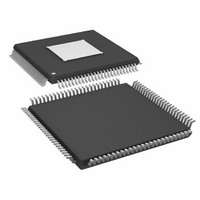
ADAU1445YSVZ-3A-RL Analog Devices Inc, ADAU1445YSVZ-3A-RL Datasheet - Page 59

ADAU1445YSVZ-3A-RL
Manufacturer Part Number
ADAU1445YSVZ-3A-RL
Description
175MHZ SigmaDSP,2x8 SRCs
Manufacturer
Analog Devices Inc
Series
SigmaDSP®r
Type
Audio Processorr
Specifications of ADAU1445YSVZ-3A-RL
Applications
Automotive Audio
Mounting Type
Surface Mount
Package / Case
100-TQFP Exposed Pad, 100-eTQFP, 100-HTQFP, 100-VQFP
Format
Fixed Point
Program Memory Size
Not RequiredKB
Operating Supply Voltage (typ)
1.8/3.3V
Operating Temp Range
-40C to 105C
Operating Temperature Classification
Industrial
Mounting
Surface Mount
Pin Count
100
Lead Free Status / RoHS Status
Lead free / RoHS Compliant
Lead Free Status / RoHS Status
Lead free / RoHS Compliant
Available stocks
Company
Part Number
Manufacturer
Quantity
Price
Company:
Part Number:
ADAU1445YSVZ-3A-RL
Manufacturer:
Analog Devices Inc
Quantity:
10 000
Numeric Formats
DSP systems commonly use a standard numeric format.
Fractional number systems are specified by an A.B format,
where A is the number of bits to the left of the decimal point
and B is the number of bits to the right of the decimal point.
The ADAU1445/ADAU1446 use the same numeric format for
both the parameter and data values. The format is as shown in
the Numerical Format: 5.23 section.
Numerical Format: 5.23
Linear range: –16.0 to (+16.0 − 1 LSB)
Examples:
1000 0000 0000 0000 0000 0000 0000 = −16.0
1110 0000 0000 0000 0000 0000 0000 = −4.0
1111 1000 0000 0000 0000 0000 0000 = −1.0
1111 1110 0000 0000 0000 0000 0000 = −0.25
1111 1111 0011 0011 0011 0011 0011 = −0.1
1111 1111 1111 1111 1111 1111 1111 = (1 LSB below 0.0)
0000 0000 0000 0000 0000 0000 0000 = 0.0
0000 0000 1100 1100 1100 1100 1101 = 0.1
0000 0010 0000 0000 0000 0000 0000 = 0.25
0000 1000 0000 0000 0000 0000 0000 = 1.0
0010 0000 0000 0000 0000 0000 0000 = 4.0
0111 1111 1111 1111 1111 1111 1111 = (16.0 – 1 LSB).
The serial port accepts up to 24 bits of input and is sign-
extended to the full 28 bits of the DSP core. This allows internal
gains of up to 24 dB without encountering internal clipping.
A digital clipper circuit is used within the DSP core before
outputting to the serial port outputs, ASRCs, and S/PDIF
transmitter (see Figure 52). This clips the top four bits of the
signal to produce a 24-bit output with a range of 1.0 (minus
1 LSB) to –1.0. Figure 52 shows the maximum signal levels at
each point in the data flow in both binary and decibel levels.
SDATA_INx
Programming
On power-up, the ADAU1445/ADAU1446 have no default
program loaded. There are 3584 instruction cycles per audio
sample, resulting in an internal clock rate of 172.032 MHz when
f
meaning that all 3584 instructions are executed each sample
period. The ADAU1445/ADAU1446 can also be set up to accept
dual- or quad-speed inputs by reducing the number of
instructions per sample. These modes can be set in the core
control register.
S,NORMAL
Figure 52. Numeric Precision and Clipping Structure (TBD)
is 48 kHz. The DSP runs in a stream-oriented manner,
1.23
(0dB)
SERIAL
PORT
4-BIT SIGN EXTENSION
(0dB)
1.23
5.23
(24dB)
(5.23 FORMAT)
PROCESSING
SIGNAL
(24dB)
5.23
CLIPPER
DIGITAL
(0dB)
1.23
Rev. A | Page 59 of 92
The ADAU1445/ADAU1446 can be programmed easily using
SigmaStudio, an entirely graphical tool provided by Analog
Devices. No knowledge of writing line-level DSP code is required,
and the large library of predesigned algorithms should drastically
reduce development time. More information on SigmaStudio
can be found at the Analog Devices website.
Program Counter
The execution of instructions in the core is governed by a
program counter, which sequentially steps through the
addresses of the program RAM. The program counter starts
every time a new audio frame is clocked into the core.
SigmaStudio inserts a jump-to-start command at the end of
every program. The program counter increments sequentially
until reaching this command, and then jumps to the program
start address (Program RAM Address 0x2010 ) and waits for the
next audio frame to clock into the core.
Branching and Looping
Some cells in SigmaStudio can optionally modify the program
counter to implement simple branching and looping structures.
However, care must be taken that the program counter returns
to its starting address before a new frame is clocked. If the new
frame starts before the counter has returned to start, the audio
output is corrupted, and a reset is necessary.
The software compiler in SigmaStudio calculates the maximum
possible program cycles for a given project and generates an
error when a user exceeds the allowable limit.
DSP CORE MODES AND SETTINGS
Core Run Register (Address 0xE228)
Table 39. Descriptions of Register 0xE228
Bit Position
[15:1]
[0]
This single-bit register initiates the run signal to start the core.
This should be the very last register that is set when the system
is initialized.
If the core is halted (that is, if Bit 0 of Register 0xE228 is set to
0) during operation, the serial outputs slew to 0. This ensures
that no dc level is left on the serial outputs and helps prevent
speaker damage in the system. It also allows the system to mute
and unmute all audio channels while minimizing pops and
clicks on the outputs.
The core run bit can be used to implement a system mute
functionality, as opposed to muting all of the individual
channels in software.
Description
Reserved
Core run bit
ADAU1445/ADAU1446
Default
0


