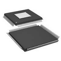
ADAU1445YSVZ-3A-RL Analog Devices Inc, ADAU1445YSVZ-3A-RL Datasheet - Page 29

ADAU1445YSVZ-3A-RL
Manufacturer Part Number
ADAU1445YSVZ-3A-RL
Description
175MHZ SigmaDSP,2x8 SRCs
Manufacturer
Analog Devices Inc
Series
SigmaDSP®r
Type
Audio Processorr
Specifications of ADAU1445YSVZ-3A-RL
Applications
Automotive Audio
Mounting Type
Surface Mount
Package / Case
100-TQFP Exposed Pad, 100-eTQFP, 100-HTQFP, 100-VQFP
Format
Fixed Point
Program Memory Size
Not RequiredKB
Operating Supply Voltage (typ)
1.8/3.3V
Operating Temp Range
-40C to 105C
Operating Temperature Classification
Industrial
Mounting
Surface Mount
Pin Count
100
Lead Free Status / RoHS Status
Lead free / RoHS Compliant
Lead Free Status / RoHS Status
Lead free / RoHS Compliant
Available stocks
Company
Part Number
Manufacturer
Quantity
Price
Company:
Part Number:
ADAU1445YSVZ-3A-RL
Manufacturer:
Analog Devices Inc
Quantity:
10 000
SERIAL DATA INPUT/OUTPUT
The flexible serial data input and output ports of the ADAU1445/
ADAU1446 can be set to accept or transmit data in a 2-channel
(usually I
channel TDM stream. Data is processed in twos complement,
MSB-first format. The left-channel data field always precedes
the right-channel data field in 2-channel streams. In the TDMn
modes (where n represents the total number of channels in the
stream), Slot 0 to Slot (n/2) − 1 fall in the first half of the audio
frame, and Slot n/2 to Slot n − 1 are in the second half of the
frame. TDM mode allows fewer serial data pins to be used,
freeing more pins for other data streams. The serial modes are
set in the serial output port modes and serial input port modes
control registers.
When referring to audio data streams, the terms TDM2 and I
should be treated with care. In this document, TDM2 refers to
any 2-channel stream, whereas I
negative BCLK polarity, negative LRCLK polarity, MSB delay-
by-1 stream.
The serial data clocks are fully bidirectional and do not need to
be synchronous with the ADAU1445/ADAU1446 master clock
input. However, asynchronous data streams must be routed
through an on-board asynchronous sample rate converter to
be processed in the core.
The input control registers allow control of clock polarity and data
input modes. All common data formats are available with flexible
MSB start, bit depth (24-, 20-, or 16-bit), and TDM settings. In all
modes except for the right-justified modes, the serial port accepts
an arbitrary number of bits up to a limit of 24. Extra bits do not
cause an error, but they are truncated internally. Proper operation
of the right-justified modes requires that there be exactly 64 BCLKs
per audio frame (for 2-channel data). The LRCLK in TDM mode
can be input to the ADAU1445/ADAU1446 either as a 50/50 duty
cycle clock or as a bit-wide pulse.
In TDM mode, the bit clock supplied by the ADAU1445/
ADAU1446 in master mode is limited to 25 MHz. This, in turn,
limits the sampling rate at which it can supply master clocks in
various TDM modes. Table 16 displays the modes in which the
serial output port functions for some common audio sample rates.
The output control registers give the user control of clock polarities,
clock frequencies, clock types, and data format. In all modes except
2
S format), packed TDM4, or standard 4-, 8-, or 16-
2
S refers specifically to a 2-channel,
Rev. A | Page 29 of 92
2
S
the right-justified modes (MSB delayed by 8, 12, or 16), the serial
port accepts an arbitrary number of bits up to a limit of 24.
Extra bits do not cause an error, but are truncated internally.
Proper operation of the right-justified modes requires the LSB
to align with the edge of the LRCLK. The default settings of all
serial port control registers correspond to 2-channel, I
and 24-bit slave mode, and these registers are set as slaves to the
clock domain corresponding to their channel number.
Table 16. Serial Input and Output Port TDM Capabilities
Mode
TDM2
TDM4
TDM8
TDM16
1
Connections to an external DAC are handled exclusively with
the output port pins. The output LRCLKx and BCLKx pins can
be set to be either master or slave, and the SDATA_OUT pins
are used to output data from the SigmaDSP to the external DAC.
Table 17 shows the proper configurations for standard audio
data formats, and Figure 21 presents an overview of the serial
data input/output ports.
The device will not work in this mode.
BCLK Cycles
per Frame
64
64
64
64
64
128
128
128
128
128
256
256
256
256
256
512
512
512
512
512
44.1
44.1
44.1
44.1
f
48
88.2
96
192
48
88.2
96
192
48
88.2
96
192
48
88.2
96
192
S
(kHz)
ADAU1445/ADAU1446
BCLK
Frequency (MHz)
2.8224
3.072
5.6448
6.144
12.288
5.6448
6.144
11.2896
12.288
24.576
11.2896
12.288
22.5792
24.576
49.152
22.5792
24.576
45.1584
49.152
98.304
2
S mode,
Valid
Mode
Yes
Yes
Yes
Yes
Yes
Yes
Yes
Yes
Yes
Yes
Yes
Yes
Yes
Yes
No
Yes
Yes
No
No
No
1
1
1
1


