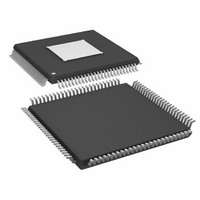
ADAU1445YSVZ-3A-RL Analog Devices Inc, ADAU1445YSVZ-3A-RL Datasheet - Page 51

ADAU1445YSVZ-3A-RL
Manufacturer Part Number
ADAU1445YSVZ-3A-RL
Description
175MHZ SigmaDSP,2x8 SRCs
Manufacturer
Analog Devices Inc
Series
SigmaDSP®r
Type
Audio Processorr
Specifications of ADAU1445YSVZ-3A-RL
Applications
Automotive Audio
Mounting Type
Surface Mount
Package / Case
100-TQFP Exposed Pad, 100-eTQFP, 100-HTQFP, 100-VQFP
Format
Fixed Point
Program Memory Size
Not RequiredKB
Operating Supply Voltage (typ)
1.8/3.3V
Operating Temp Range
-40C to 105C
Operating Temperature Classification
Industrial
Mounting
Surface Mount
Pin Count
100
Lead Free Status / RoHS Status
Lead free / RoHS Compliant
Lead Free Status / RoHS Status
Lead free / RoHS Compliant
Available stocks
Company
Part Number
Manufacturer
Quantity
Price
Company:
Part Number:
ADAU1445YSVZ-3A-RL
Manufacturer:
Analog Devices Inc
Quantity:
10 000
ASRC Input Select Pairs[7:0] Registers
(Address 0xE080 to Address 0xE087)
The inputs to each of the eight ASRCs can come from any stereo
pair from either the serial input channels or the DSP core.
In the case of the ADAU1445, each input to the stereo ASRCs
can receive a separate data input; however, all inputs to Stereo
ASRC[3:0] must be synchronous to each other, and all inputs
Table 31. Bit Descriptions of ASRC Input Select Pairs[7:0] Registers
Bit Position
[15:6]
[5:0]
Description
Reserved
ASRC input data selector
000000 = Serial Input Pair 0 (Channel 0, Channel 1)
000001 = Serial Input Pair 1 (Channel 2, Channel 3)
000010 = Serial Input Pair 2 (Channel 4, Channel 5)
000011 = Serial Input Pair 3 (Channel 6, Channel 7)
000100 = Serial Input Pair 4 (Channel 8, Channel 9)
000101 = Serial Input Pair 5 (Channel 10, Channel 11)
000110 = Serial Input Pair 6 (Channel 12, Channel 13)
000111 = Serial Input Pair 7 (Channel 14, Channel 15)
001000 = Serial Input Pair 8 (Channel 16, Channel 17)
001001 = Serial Input Pair 9 (Channel 18, Channel 19)
001010 = Serial Input Pair 10 (Channel 20, Channel 21)
001011 = Serial Input Pair 11 (Channel 22, Channel 23)
010000 = DSP-to-ASRC Pair 0 (Channel 0, Channel 1)
010001 = DSP-to-ASRC Pair 1 (Channel 2, Channel 3)
010010 = DSP-to-ASRC Pair 2 (Channel 4, Channel 5)
010011 = DSP-to-ASRC Pair 3 (Channel 6, Channel 7)
010100 = DSP-to-ASRC Pair 4 (Channel 8, Channel 9)
010101 = DSP-to-ASRC Pair 5 (Channel 10, Channel 11)
010110 = DSP-to-ASRC Pair 6 (Channel 12, Channel 13)
010111 = DSP-to-ASRC Pair 7 (Channel 14, Channel 15)
100000 = S/PDIF Receiver Pair 0 (Channel 0, Channel 1)
111111 = no data
Rev. A | Page 51 of 92
to Stereo ASRC[7:4] must be synchronous to each other. The first
group of ASRCs (Stereo ASRC[3:0]) takes its input rate from the
Stereo ASRC 0 input, and the second group of ASRCs (Stereo
ASRC[7:4]) takes its input rate from Stereo ASRC 4 input.
In the case of the ADAU1446, which contains no ASRCs, these
registers do not affect system operation in any way and can be
ignored.
ADAU1445/ADAU1446
Default
111111


