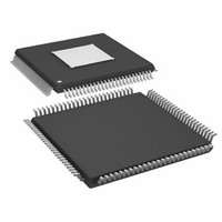
ADAU1445YSVZ-3A-RL Analog Devices Inc, ADAU1445YSVZ-3A-RL Datasheet - Page 46

ADAU1445YSVZ-3A-RL
Manufacturer Part Number
ADAU1445YSVZ-3A-RL
Description
175MHZ SigmaDSP,2x8 SRCs
Manufacturer
Analog Devices Inc
Series
SigmaDSP®r
Type
Audio Processorr
Specifications of ADAU1445YSVZ-3A-RL
Applications
Automotive Audio
Mounting Type
Surface Mount
Package / Case
100-TQFP Exposed Pad, 100-eTQFP, 100-HTQFP, 100-VQFP
Format
Fixed Point
Program Memory Size
Not RequiredKB
Operating Supply Voltage (typ)
1.8/3.3V
Operating Temp Range
-40C to 105C
Operating Temperature Classification
Industrial
Mounting
Surface Mount
Pin Count
100
Lead Free Status / RoHS Status
Lead free / RoHS Compliant
Lead Free Status / RoHS Status
Lead free / RoHS Compliant
Available stocks
Company
Part Number
Manufacturer
Quantity
Price
Company:
Part Number:
ADAU1445YSVZ-3A-RL
Manufacturer:
Analog Devices Inc
Quantity:
10 000
ADAU1445/ADAU1446
Flexible Audio Routing Matrix—Input Side
Up until this point in the audio signal flow, all signals can be
asynchronous to each other. However, before entering the DSP
for processing, the signals must be synchronized to the same
clock. Therefore, on the input side of the routing matrix, the
input channels can be routed, if desired, to the ASRCs for
sample rate conversion. The input side of the routing matrix is
represented in Figure 39 as a large gray box.
As shown in Figure 39, Input Channels[23:0] are hardwired
to DSP Inputs[23:0]. However, Input Channels[23:0] are also
available at the input side of FARM to be routed to the ASRCs.
CHANNELS
(24 CH)
S/PDIF Rx
INPUT
Figure 39. Flexible Audio Routing Matrix—Input Side
10, 11
12, 13
14, 15
16, 17
18, 19
20, 21
22, 23
0, 1
2, 3
4, 5
6, 7
8, 9
10, 11
12, 13
14, 15
16, 17
18, 19
20, 21
22, 23
0, 1
2, 3
4, 5
6, 7
8, 9
FROM DSP
DSP
10, 11
12, 13
14, 15
0, 1
2, 3
4, 5
6, 7
8, 9
TO ASRCs
Rev. A | Page 46 of 92
Note that there are 13 channel pairs available on the left side of
FARM (12 input channel pairs and one S/PDIF Rx pair) and
eight channel pairs coming from the top (DSP-to-ASRC pairs).
These make up the 21 input channel pairs available to the input
side of the routing matrix. In the lower right, there are eight
channel pairs output from the routing matrix (inputs to the
ASRCs). These make up the eight output channel pairs available
to the input side of the routing matrix. Because audio is always
routed in pairs, a one-to-one connection can be made between
any input pair and any output pair. Therefore, any input channel
pair, S/PDIF Rx channel pair, or DSP-to-ASRC channel pair can
be connected to any ASRC input pair. Any combination is
possible, as long as a one-to-one relationship is maintained.
Note that most applications require sample rate conversion of
the S/PDIF Rx signal.
In the case of the ADAU1445, there are two 8-channel ASRCs.
Therefore, Stereo ASRC Input Pairs[3:0] (composed of Channel 0
to Channel 7) correspond to the first ASRC (Stereo ASRC[3:0])
and must be synchronous to each other. Stereo ASRC Input
Pairs[7:4] (composed of Channel 8 to Channel 15) correspond
to the second ASRC (Stereo ASRC[7:4]), and must be synchronous
to each other.
In the case of the ADAU1446, there are no sample rate converters;
therefore, after the automatic channel assignment, the stereo input
pairs are hardwired to the DSP core and the input side of the
routing matrix is not used. This is shown in Figure 40.
SDATA_IN0
SDATA_IN1
SDATA_IN2
SDATA_IN3
SDATA_IN4
SDATA_IN5
SDATA_IN6
SDATA_IN7
SDATA_IN8
Figure 40. Input Routing in the ADAU1446
SERIAL
SERIAL
MODES
PORTS
INPUT
INPUT
(×9)
CHANNELS
(24 CH)
INPUT
0, 1
2, 3
4, 5
6, 7
8, 9
10, 11
12, 13
14, 15
16, 17
18, 19
20, 21
22, 23
DSP CORE
SERIAL I/O
(24 CH)


