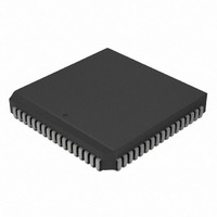
PIC18C801-I/L Microchip Technology, PIC18C801-I/L Datasheet - Page 50

PIC18C801-I/L
Manufacturer Part Number
PIC18C801-I/L
Description
IC,MICROCONTROLLER,8-BIT,PIC CPU,CMOS,LDCC,84PIN,PLASTIC
Manufacturer
Microchip Technology
Series
PIC® 18Cr
Datasheets
1.PIC16F616T-ISL.pdf
(8 pages)
2.PIC18C601-IL.pdf
(320 pages)
3.PIC18C601-IL.pdf
(10 pages)
4.PIC18C601-IL.pdf
(10 pages)
Specifications of PIC18C801-I/L
Rohs Compliant
YES
Core Processor
PIC
Core Size
8-Bit
Speed
25MHz
Connectivity
EBI/EMI, I²C, SPI, UART/USART
Peripherals
Brown-out Detect/Reset, LVD, POR, PWM, WDT
Number Of I /o
37
Program Memory Type
ROMless
Ram Size
1.5K x 8
Voltage - Supply (vcc/vdd)
4.2 V ~ 5.5 V
Data Converters
A/D 12x10b
Oscillator Type
External
Operating Temperature
-40°C ~ 85°C
Package / Case
84-PLCC
Processor Series
PIC18C
Core
PIC
Data Bus Width
8 bit
Data Ram Size
1.5 KB
Interface Type
3-Wire, I2C, SPI, USART
Maximum Clock Frequency
25 MHz
Number Of Programmable I/os
47
Number Of Timers
1 x 16 bit
Operating Supply Voltage
2 V to 5.5 V
Maximum Operating Temperature
+ 85 C
Mounting Style
SMD/SMT
3rd Party Development Tools
52715-96, 52716-328, 52717-734, 52712-325, EWPIC18
Development Tools By Supplier
DV164005, ICE4000, DV164136
Minimum Operating Temperature
- 40 C
On-chip Adc
10 bit
Lead Free Status / RoHS Status
Lead free / RoHS Compliant
For Use With
AC164310 - MODULE SKT FOR PM3 84PLCCXLT84L1 - SOCKET TRANSITION ICE 84PLCCAC174012 - MODULE SKT PROMATEII 84PLCC
Eeprom Size
-
Program Memory Size
-
Lead Free Status / Rohs Status
Details
Other names
PIC18C801-I/LR
PIC18C801-I/LR
PIC18C801I/L
PIC18C801-I/LR
PIC18C801I/L
Available stocks
Company
Part Number
Manufacturer
Quantity
Price
Company:
Part Number:
PIC18C801-I/L
Manufacturer:
MICROCHIP
Quantity:
12 000
Company:
Part Number:
PIC18C801-I/L
Manufacturer:
Microchip Technology
Quantity:
10 000
- PIC16F616T-ISL PDF datasheet
- PIC18C601-IL PDF datasheet #2
- PIC18C601-IL PDF datasheet #3
- PIC18C601-IL PDF datasheet #4
- Current page: 50 of 320
- Download datasheet (6Mb)
PIC18C601/801
REGISTER 4-2:
The Combination Lock bits must be set sequentially,
meaning that as soon as Combination Lock bit CMLK1
is set, the second Combination Lock bit CMLK0 must be
set on the following instruction cycle. If user waits more
than one machine cycle to set the second bit after set-
ting the first, both bits will automatically be cleared in
hardware and the lock will remain closed. To satisfy this
condition, all interrupts must be disabled before attempt-
ing to unlock the Combination Lock. Once secured reg-
isters are modified, interrupts may be re-enabled.
Each instruction must only modify one combination lock
bit at a time. This means, user code must use the BSF
instruction to set CMLK bits in the PSPCON register.
EXAMPLE 4-4:
DS39541A-page 50
Note:
MOVLW 5Ah
BCF INTCON, GIE
CALL UNLOCK
MOVWF OSCCON
BSF INTCON, GIE
UNLOCK
BSF PSPCON, CMLK1
BSF PSPCON, CMLK0
RETURN
bit 7-2
bit 1-0
The Combination Lock bits are write-only
bits. These bits will always return ‘0’ when
read.
PSPCON REGISTER
COMBINATION UNLOCK SUBROUTINE EXAMPLE CODE
bit 7
Unimplemented: Read as '0'
CMLK<1:0>: Combination Lock bits
Legend:
R = Readable bit
- n = Value at POR
U-0
—
; Preload WREG with data to be stored in a safety critical register
; Disable all interrupts
; Now unlock it
; Write must take place in next instruction cycle
; Lock is closed
; Re-enable interrupts
U-0
—
Advance Information
U-0
—
W = Writable bit
’1’ = Bit is set
U-0
When the Combination Lock is opened, the user will
have three instruction cycles to modify the safety criti-
cal register of choice. After three instruction cycles
have expired, the CMLK bits are cleared, the lock will
close and the user will have to set the CMLK bits again,
in order to open the lock. Since there are only three
instruction cycles allowed after the Combination Lock is
opened, if a subroutine is used to unlock Combination
Lock bits, user code must preload WREG with the
desired value, call unlock subroutine, and write to the
desired safety critical register itself.
—
Note:
U = Unimplemented bit, read as ‘0’
’0’ = Bit is cleared
Successive attempts to unlock the Combi-
nation Lock must be separated by at least
three instruction cycles.
U-0
—
U-0
—
2001 Microchip Technology Inc.
x = Bit is unknown
CMLK1
W-0
CMLK0
W-0
bit 0
Related parts for PIC18C801-I/L
Image
Part Number
Description
Manufacturer
Datasheet
Request
R

Part Number:
Description:
IC, 8BIT MCU, PIC18F, 40MHZ, LCC-44
Manufacturer:
Microchip Technology
Datasheet:

Part Number:
Description:
IC, 8BIT MCU, PIC18LF, 40MHZ, PLCC-64
Manufacturer:
Microchip Technology
Datasheet:

Part Number:
Description:
IC, 8BIT MCU, PIC18F, 64MHZ, TQFP-80
Manufacturer:
Microchip Technology
Datasheet:

Part Number:
Description:
MCU, MPU & DSP Development Tools CAN/LIN PICtail Plus Daughter Board
Manufacturer:
Microchip Technology
Datasheet:

Part Number:
Description:
IC, 8BIT MCU, PIC18F, 64MHZ, DIP-40
Manufacturer:
Microchip Technology
Datasheet:

Part Number:
Description:
IC, 8BIT MCU, PIC18LF, 40MHZ, PLCC-64
Manufacturer:
Microchip Technology
Datasheet:

Part Number:
Description:
IC, 8BIT MCU, PIC18F, 64MHZ, TQFP-64
Manufacturer:
Microchip Technology

Part Number:
Description:
IC, 8BIT MCU, PIC18F, 64MHZ, TQFP-80
Manufacturer:
Microchip Technology

Part Number:
Description:
8KB, Flash, 768bytes-RAM, 36I/O, 8-bit Family,nanowatt XLP 40 UQFN 5x5x0.5mm TUB
Manufacturer:
Microchip Technology
Datasheet:

Part Number:
Description:
8KB, Flash, 768bytes-RAM, 36I/O, 8-bit Family,nanowatt XLP 40 UQFN 5x5x0.5mm TUB
Manufacturer:
Microchip Technology

Part Number:
Description:
16KB, Flash, 768bytes-RAM, 36I/O, 8-bit Family,nanowatt XLP 40 UQFN 5x5x0.5mm TU
Manufacturer:
Microchip Technology
Datasheet:

Part Number:
Description:
16KB, Flash, 768bytes-RAM, 36I/O, 8-bit Family,nanowatt XLP 40 UQFN 5x5x0.5mm TU
Manufacturer:
Microchip Technology

Part Number:
Description:
32KB, Flash, 1536bytes-RAM, 36I/O, 8-bit Family,nanowatt XLP 40 UQFN 5x5x0.5mm T
Manufacturer:
Microchip Technology
Datasheet:

Part Number:
Description:
32KB, Flash, 1536bytes-RAM, 36I/O, 8-bit Family,nanowatt XLP 40 UQFN 5x5x0.5mm T
Manufacturer:
Microchip Technology

Part Number:
Description:
64KB, Flash, 3968bytes-RAM, 36I/O, 8-bit Family,nanowatt XLP 40 UQFN 5x5x0.5mm T
Manufacturer:
Microchip Technology
Datasheet:


