PIC18C801-I/L Microchip Technology, PIC18C801-I/L Datasheet - Page 183
PIC18C801-I/L
Manufacturer Part Number
PIC18C801-I/L
Description
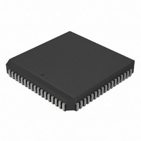
IC,MICROCONTROLLER,8-BIT,PIC CPU,CMOS,LDCC,84PIN,PLASTIC
Manufacturer
Microchip Technology
Series
PIC® 18Cr
Datasheets
1.PIC16F616T-ISL.pdf
(8 pages)
2.PIC18C601-IL.pdf
(320 pages)
3.PIC18C601-IL.pdf
(10 pages)
4.PIC18C601-IL.pdf
(10 pages)
Specifications of PIC18C801-I/L
Rohs Compliant
YES
Core Processor
PIC
Core Size
8-Bit
Speed
25MHz
Connectivity
EBI/EMI, I²C, SPI, UART/USART
Peripherals
Brown-out Detect/Reset, LVD, POR, PWM, WDT
Number Of I /o
37
Program Memory Type
ROMless
Ram Size
1.5K x 8
Voltage - Supply (vcc/vdd)
4.2 V ~ 5.5 V
Data Converters
A/D 12x10b
Oscillator Type
External
Operating Temperature
-40°C ~ 85°C
Package / Case
84-PLCC
Processor Series
PIC18C
Core
PIC
Data Bus Width
8 bit
Data Ram Size
1.5 KB
Interface Type
3-Wire, I2C, SPI, USART
Maximum Clock Frequency
25 MHz
Number Of Programmable I/os
47
Number Of Timers
1 x 16 bit
Operating Supply Voltage
2 V to 5.5 V
Maximum Operating Temperature
+ 85 C
Mounting Style
SMD/SMT
3rd Party Development Tools
52715-96, 52716-328, 52717-734, 52712-325, EWPIC18
Development Tools By Supplier
DV164005, ICE4000, DV164136
Minimum Operating Temperature
- 40 C
On-chip Adc
10 bit
Lead Free Status / RoHS Status
Lead free / RoHS Compliant
For Use With
AC164310 - MODULE SKT FOR PM3 84PLCCXLT84L1 - SOCKET TRANSITION ICE 84PLCCAC174012 - MODULE SKT PROMATEII 84PLCC
Eeprom Size
-
Program Memory Size
-
Lead Free Status / Rohs Status
Details
Other names
PIC18C801-I/LR
PIC18C801-I/LR
PIC18C801I/L
PIC18C801-I/LR
PIC18C801I/L
Available stocks
Company
Part Number
Manufacturer
Quantity
Price
Company:

Part Number:
PIC18C801-I/L
Manufacturer:
MICROCHIP
Quantity:
12 000
Company:
Part Number:
PIC18C801-I/L
Manufacturer:
Microchip Technology
Quantity:
10 000


16.2
In this mode, data is transmitted in non-return-to-zero
(NRZ) format. Data consists of one START bit, eight or
nine data bits and one STOP bit. Data is transmitted in
serial fashion with LSb first. An on-chip 8-bit baud rate
generator can be programmed to generate the desired
baud rate. The baud rate generator produces a clock,
either x16 or x64 of the bit shift rate, depending on the
BRGH bit (TXSTA register). USART does not automat-
ically calculate the parity bit for the given data byte. If
parity is to be transmitted, USART must be pro-
grammed to transmit nine bits and software must set/
clear ninth data bit as parity bit. Asynchronous mode is
stopped during SLEEP.
Asynchronous mode is selected by clearing the SYNC
bit (TXSTA register).
The USART Asynchronous module consists of the fol-
lowing important elements:
• Baud Rate Generator
• Sampling Circuit
• Asynchronous Transmitter
• Asynchronous Receiver
16.2.1
The USART transmitter block diagram is shown in
Figure 16-1. The heart of the transmitter is the Transmit
(serial) Shift Register (TSR). The TSR register obtains
its data from the Read/Write Transmit Buffer register
(TXREG). The TXREG register is loaded with data in
software. The TSR register is not loaded until the STOP
bit has been transmitted from the previous load. As
soon as the STOP bit is transmitted, the TSR is loaded
with new data from the TXREG register (if available).
FIGURE 16-1:
2001 Microchip Technology Inc.
Note:
I/O pins have diode protection to V
USART Asynchronous Mode
USART ASYNCHRONOUS
TRANSMITTER
TXIE
Interrupt
USART TRANSMIT BLOCK DIAGRAM
TXEN
TXIF
Baud Rate Generator
SPBRG
Baud Rate CLK
DD
and V
MSb
(8)
SS
Advance Information
.
TX9D
TXREG Register
TSR Register
TX9
8
Data Bus
Once the TXREG register transfers the data to the TSR
register (occurs in one T
empty and flag bit TXIF (PIR registers) is set. This inter-
rupt can be enabled/disabled by setting/clearing
enable bit TXIE (PIE registers). Flag bit TXIF will be
set, regardless of the state of enable bit TXIE and can-
not be cleared in software. It will reset only when new
data is loaded into the TXREG register. While flag bit
TXIF indicated the status of the TXREG register,
another bit TRMT (TXSTA register) shows the status of
the TSR register. Status bit TRMT is a read only bit,
which is set when the TSR register is empty. No inter-
rupt logic is tied to this bit, so the user has to poll this
bit in order to determine if the TSR register is empty.
Steps to follow when setting up an Asynchronous
Transmission:
1.
2.
3.
4.
5.
6.
7.
Note 1: The TSR register is not mapped in data
Initialize the SPBRG register for the appropriate
baud rate. If a high speed baud rate is desired,
set bit BRGH (Section 16.1).
Enable the asynchronous serial port by clearing
bit SYNC and setting bit SPEN.
If interrupts are desired, set enable bit TXIE.
If 9-bit transmission is desired, set transmit bit
TX9. Can be used as address/data bit.
Enable the transmission by setting bit TXEN,
which will also set bit TXIF.
If 9-bit transmission is selected, the ninth bit
should be loaded in bit TX9D.
Load data to the TXREG register (starts trans-
mission).
LSb
0
2: Flag bit TXIF is set when enable bit TXEN
memory, so it is not available to the user.
TRMT
is set.
PIC18C601/801
Pin Buffer
and Control
SPEN
CY
), the TXREG register is
RC6/TX/CK pin
DS39541A-page 183
Related parts for PIC18C801-I/L
Image
Part Number
Description
Manufacturer
Datasheet
Request
R

Part Number:
Description:
IC, 8BIT MCU, PIC18F, 40MHZ, LCC-44
Manufacturer:
Microchip Technology
Datasheet:
Part Number:
Description:
IC, 8BIT MCU, PIC18LF, 40MHZ, PLCC-64
Manufacturer:
Microchip Technology
Datasheet:
Part Number:
Description:
IC, 8BIT MCU, PIC18F, 64MHZ, TQFP-80
Manufacturer:
Microchip Technology
Datasheet:

Part Number:
Description:
MCU, MPU & DSP Development Tools CAN/LIN PICtail Plus Daughter Board
Manufacturer:
Microchip Technology
Datasheet:

Part Number:
Description:
IC, 8BIT MCU, PIC18F, 64MHZ, DIP-40
Manufacturer:
Microchip Technology
Datasheet:

Part Number:
Description:
IC, 8BIT MCU, PIC18LF, 40MHZ, PLCC-64
Manufacturer:
Microchip Technology
Datasheet:
Part Number:
Description:
IC, 8BIT MCU, PIC18F, 64MHZ, TQFP-64
Manufacturer:
Microchip Technology
Part Number:
Description:
IC, 8BIT MCU, PIC18F, 64MHZ, TQFP-80
Manufacturer:
Microchip Technology

Part Number:
Description:
8KB, Flash, 768bytes-RAM, 36I/O, 8-bit Family,nanowatt XLP 40 UQFN 5x5x0.5mm TUB
Manufacturer:
Microchip Technology
Datasheet:
Part Number:
Description:
8KB, Flash, 768bytes-RAM, 36I/O, 8-bit Family,nanowatt XLP 40 UQFN 5x5x0.5mm TUB
Manufacturer:
Microchip Technology
Part Number:
Description:
16KB, Flash, 768bytes-RAM, 36I/O, 8-bit Family,nanowatt XLP 40 UQFN 5x5x0.5mm TU
Manufacturer:
Microchip Technology
Datasheet:
Part Number:
Description:
16KB, Flash, 768bytes-RAM, 36I/O, 8-bit Family,nanowatt XLP 40 UQFN 5x5x0.5mm TU
Manufacturer:
Microchip Technology
Part Number:
Description:
32KB, Flash, 1536bytes-RAM, 36I/O, 8-bit Family,nanowatt XLP 40 UQFN 5x5x0.5mm T
Manufacturer:
Microchip Technology
Datasheet:
Part Number:
Description:
32KB, Flash, 1536bytes-RAM, 36I/O, 8-bit Family,nanowatt XLP 40 UQFN 5x5x0.5mm T
Manufacturer:
Microchip Technology
Part Number:
Description:
64KB, Flash, 3968bytes-RAM, 36I/O, 8-bit Family,nanowatt XLP 40 UQFN 5x5x0.5mm T
Manufacturer:
Microchip Technology
Datasheet: