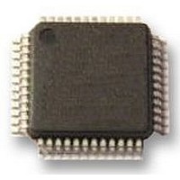
UPD78F0413GA-GAM-AX NEC, UPD78F0413GA-GAM-AX Datasheet - Page 9

UPD78F0413GA-GAM-AX
Manufacturer Part Number
UPD78F0413GA-GAM-AX
Description
8BIT UC, 32K FLASH, 1KB RAM, LCD
Manufacturer
NEC
Datasheet
1.UPD78F0413GA-GAM-AX.pdf
(562 pages)
Specifications of UPD78F0413GA-GAM-AX
Controller Family/series
UPD78F
No. Of I/o's
30
Ram Memory Size
1024Byte
Cpu Speed
10MHz
No. Of Timers
8
No. Of Pwm
RoHS Compliant
Core Size
8bit
Program Memory Size
32KB
Oscillator Type
External, Internal
Available stocks
Company
Part Number
Manufacturer
Quantity
Price
Company:
Part Number:
UPD78F0413GA-GAM-AX
Manufacturer:
ADI
Quantity:
882
Company:
Part Number:
UPD78F0413GA-GAM-AX
Manufacturer:
Renesas Electronics America
Quantity:
10 000
- Current page: 9 of 562
- Download datasheet (4Mb)
CHAPTER 6 16-BIT TIMER/EVENT COUNTER 00........................................................................... 143
CHAPTER 7 8-BIT TIMER/EVENT COUNTERS 50, 51, AND 52 .................................................. 218
CHAPTER 8 8-BIT TIMERS H0, H1 AND H2................................................................................... 234
6.1 Functions of 16-Bit Timer/Event Counter 00 ........................................................................... 143
6.2 Configuration of 16-Bit Timer/Event Counter 00..................................................................... 144
6.3 Registers Controlling 16-Bit Timer/Event Counter 00 ............................................................ 149
6.4 Operation of 16-Bit Timer/Event Counter 00 ........................................................................... 158
6.5 Special Use of TM00 .................................................................................................................. 212
6.6 Cautions for 16-Bit Timer/Event Counter 00 ........................................................................... 214
7.1 Functions of 8-Bit Timer/Event Counters 50, 51, and 52 ....................................................... 218
7.2 Configuration of 8-Bit Timer/Event Counters 50, 51, and 52 ................................................. 218
7.3 Registers Controlling 8-Bit Timer/Event Counters 50, 51, and 52 ........................................ 222
7.4 Operations of 8-Bit Timer/Event Counters 50, 51, and 52...................................................... 229
7.5 Cautions for 8-Bit Timer/Event Counters 50, 51, and 52........................................................ 232
8.1 Functions of 8-Bit Timers H0, H1, and H2 ............................................................................... 234
8.2 Configuration of 8-Bit Timers H0, H1, and H2 ......................................................................... 234
8.3 Registers Controlling 8-Bit Timers H0, H1, and H2 ................................................................ 239
8.4 Operation of 8-Bit Timers H0, H1 and H2................................................................................. 246
5.6.1 Example of controlling high-speed system clock ...........................................................................127
5.6.2 Example of controlling internal high-speed oscillation clock ..........................................................129
5.6.3 Example of controlling subsystem clock ........................................................................................131
5.6.4 Example of controlling internal low-speed oscillation clock............................................................133
5.6.5 Clocks supplied to CPU and peripheral hardware .........................................................................133
5.6.6 CPU clock status transition diagram ..............................................................................................134
5.6.7 Condition before changing CPU clock and processing after changing CPU clock .........................139
5.6.8 Time required for switchover of CPU clock and main system clock ...............................................140
5.6.9 Conditions before clock oscillation is stopped................................................................................141
5.6.10 Peripheral hardware and source clocks .......................................................................................142
6.4.1 Interval timer operation ..................................................................................................................158
6.4.2 Square wave output operation .......................................................................................................161
6.4.3 External event counter operation ...................................................................................................164
6.4.4 Operation in clear & start mode entered by TI000 pin valid edge input..........................................168
6.4.5 Free-running timer operation .........................................................................................................181
6.4.6 PPG output operation ....................................................................................................................190
6.4.7 One-shot pulse output operation....................................................................................................193
6.4.8 Pulse width measurement operation..............................................................................................198
6.4.9 External 24-bit event counter operation .........................................................................................206
6.4.10 Cautions for external 24-bit event counter ...................................................................................210
6.5.1 Rewriting CR010 during TM00 operation.......................................................................................212
6.5.2 Setting LVS00 and LVR00 .............................................................................................................212
7.4.1 Operation as interval timer.............................................................................................................229
7.4.2 Operation as external event counter (TM52 only) ..........................................................................231
8.4.1 Operation as interval timer/square-wave output ............................................................................246
8.4.2 Operation as PWM output..............................................................................................................249
User’s Manual U18698EJ1V0UD
9
Related parts for UPD78F0413GA-GAM-AX
Image
Part Number
Description
Manufacturer
Datasheet
Request
R

Part Number:
Description:
16/8 bit single-chip microcomputer
Manufacturer:
NEC
Datasheet:

Part Number:
Description:
Dual audio power amp circuit
Manufacturer:
NEC
Datasheet:

Part Number:
Description:
Dual comparator
Manufacturer:
NEC
Datasheet:

Part Number:
Description:
MOS type composite field effect transistor
Manufacturer:
NEC
Datasheet:

Part Number:
Description:
50 V/100 mA FET array incorporating 2 N-ch MOSFETs
Manufacturer:
NEC
Datasheet:

Part Number:
Description:
6-pin small MM high-frequency double transistor
Manufacturer:
NEC
Datasheet:

Part Number:
Description:
6-pin small MM high-frequency double transistor
Manufacturer:
NEC
Datasheet:

Part Number:
Description:
6-pin small MM high-frequency double transistor
Manufacturer:
NEC
Datasheet:

Part Number:
Description:
6-pin small MM high-frequency double transistor
Manufacturer:
NEC
Datasheet:

Part Number:
Description:
Twin transistors equipped with different model chips(6P small MM)
Manufacturer:
NEC
Datasheet:

Part Number:
Description:
Bipolar analog integrated circuit
Manufacturer:
NEC
Datasheet:


