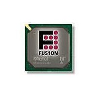
AFS600-FGG256 Actel, AFS600-FGG256 Datasheet - Page 192

AFS600-FGG256
Manufacturer Part Number
AFS600-FGG256
Description
FPGA - Field Programmable Gate Array 600K System Gates
Manufacturer
Actel
Datasheet
1.AFS600-PQG208.pdf
(330 pages)
Specifications of AFS600-FGG256
Processor Series
AFS600
Core
IP Core
Maximum Operating Frequency
1098.9 MHz
Number Of Programmable I/os
119
Data Ram Size
110592
Supply Voltage (max)
1.575 V
Maximum Operating Temperature
+ 70 C
Minimum Operating Temperature
0 C
Development Tools By Supplier
AFS-Eval-Kit, AFS-BRD600, FlashPro 3, FlashPro Lite, Silicon-Explorer II, Silicon-Sculptor 3, SI-EX-TCA
Mounting Style
SMD/SMT
Supply Voltage (min)
1.425 V
Number Of Gates
600 K
Package / Case
FPBGA-256
Lead Free Status / RoHS Status
Lead free / RoHS Compliant
Available stocks
Company
Part Number
Manufacturer
Quantity
Price
Company:
Part Number:
AFS600-FGG256
Manufacturer:
Actel
Quantity:
135
Part Number:
AFS600-FGG256
Manufacturer:
ACTEL/爱特
Quantity:
20 000
Company:
Part Number:
AFS600-FGG256I
Manufacturer:
Microsemi SoC
Quantity:
10 000
Company:
Part Number:
AFS600-FGG256K
Manufacturer:
Microsemi SoC
Quantity:
10 000
- Current page: 192 of 330
- Download datasheet (13Mb)
Device Architecture
Table 2-96 • Short Current Event Duration before Failure
Table 2-97 • Schmitt Trigger Input Hysteresis
Table 2-98 • I/O Input Rise Time, Fall Time, and Related I/O Reliability
2- 17 6
Input Buffer
LVTTL/LVCMOS (Schmitt trigger
disabled)
LVTTL/LVCMOS (Schmitt trigger
enabled)
HSTL/SSTL/GTL
LVDS/BLVDS/M-LVDS/LVPECL
Note:
Temperature
–40°C
25°C
70°C
85°C
100°C
Input Buffer Configuration
3.3 V LVTTL/LVCMOS/PCI/PCI-X (Schmitt trigger mode)
2.5 V LVCMOS (Schmitt trigger mode)
1.8 V LVCMOS (Schmitt trigger mode)
1.5 V LVCMOS (Schmitt trigger mode)
0°C
*The maximum input rise/fall time is related only to the noise induced into the input buffer trace. If the noise is
low, the rise time and fall time of input buffers, when Schmitt trigger is disabled, can be increased beyond the
maximum value. The longer the rise/fall times, the more susceptible the input signal is to the board noise. Actel
recommends signal integrity evaluation/characterization of the system to ensure there is no excessive noise
coupling into input signals.
Hysteresis Voltage Value (typ.) for Schmitt Mode Input Buffers
Input Rise/Fall Time (min.)
No requirement
No requirement
No requirement
No requirement
R e visio n 1
noise voltage cannot exceed
Schmitt hysteresis
No requirement, but input
Time before Failure
Input Rise/Fall Time (max.)
>20 years
>20 years
>20 years
6 months
5 years
2 years
Hysteresis Value (typ.)
10 ns*
10 ns*
10 ns*
240 mV
140 mV
80 mV
60 mV
20 years (100°C)
20 years (100°C)
10 years (100°C)
10 years (100°C)
Reliability
Related parts for AFS600-FGG256
Image
Part Number
Description
Manufacturer
Datasheet
Request
R

Part Number:
Description:
AFS600-1FGG256I
Manufacturer:
Actel
Datasheet:

Part Number:
Description:
AFS600-2FGG256I
Manufacturer:
Actel
Datasheet:


