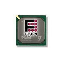
AFS600-FGG256 Actel, AFS600-FGG256 Datasheet - Page 142

AFS600-FGG256
Manufacturer Part Number
AFS600-FGG256
Description
FPGA - Field Programmable Gate Array 600K System Gates
Manufacturer
Actel
Datasheet
1.AFS600-PQG208.pdf
(330 pages)
Specifications of AFS600-FGG256
Processor Series
AFS600
Core
IP Core
Maximum Operating Frequency
1098.9 MHz
Number Of Programmable I/os
119
Data Ram Size
110592
Supply Voltage (max)
1.575 V
Maximum Operating Temperature
+ 70 C
Minimum Operating Temperature
0 C
Development Tools By Supplier
AFS-Eval-Kit, AFS-BRD600, FlashPro 3, FlashPro Lite, Silicon-Explorer II, Silicon-Sculptor 3, SI-EX-TCA
Mounting Style
SMD/SMT
Supply Voltage (min)
1.425 V
Number Of Gates
600 K
Package / Case
FPBGA-256
Lead Free Status / RoHS Status
Lead free / RoHS Compliant
Available stocks
Company
Part Number
Manufacturer
Quantity
Price
Company:
Part Number:
AFS600-FGG256
Manufacturer:
Actel
Quantity:
135
Part Number:
AFS600-FGG256
Manufacturer:
ACTEL/爱特
Quantity:
20 000
Company:
Part Number:
AFS600-FGG256I
Manufacturer:
Microsemi SoC
Quantity:
10 000
Company:
Part Number:
AFS600-FGG256K
Manufacturer:
Microsemi SoC
Quantity:
10 000
- Current page: 142 of 330
- Download datasheet (13Mb)
Device Architecture
Table 2-50 • Analog Channel Accuracy: Monitoring Standard Positive Voltages
2- 12 6
Input Voltage
(V)
15
14
12
5
3.3
2.5
1.8
1.5
1.2
0.9
Notes:
1. Requires enabling Analog Calibration using SmartGen Analog System Builder. For further details, refer to the
2. Direct ADC mode using an external VAREF of 2.56V±4.6mV, without Analog Calibration macro.
3. For input greater than 2.56 V, the ADC output will saturate. A higher VAREF or prescaler usage is recommended.
"Temperature, Voltage, and Current Calibration in Fusion FPGAs" chapter of the
Typical Conditions, T
Examples
Calculating Accuracy for an Uncalibrated Analog Channel
For a given prescaler range,
where
Formula
Channel Output offset in V = Channel Output offset in LSBs x Equivalent voltage per LSB
Channel Gain Factor = 1+ (% Channel Gain / 100)
Example
Input Voltage = 5 V
Chosen Prescaler range = 8 V range
Refer to
Max. Output Voltage = (Max Positive output offset) + (Input Voltage x Max Gain Factor)
Max. Positive output offset = (8 LSB) x (8mV per LSB in 10-bit mode)
Max. Positive output offset = 64 mV
Max. Gain = 1 + (2/100)
Max. Gain = 1.02
Max. Output Voltage = (64 mV) + (5 V x 1.02)
Max. Output Voltage = 5.164 V
Similarly,
16 V (AT)
1
1
1
2
2
3
4
5
7
9
Calibrated Typical Error per Positive Prescaler Setting
Output Voltage = (Channel Output Offset in V) + (Input Voltage x Channel Gain)
Table 2-48 on page
16 V (12 V)
(AV/AC)
1
2
2
2
4
5
6
9
A
= 25°C
EQ 24
(AV/AC)
8 V
2-124.
1
1
1
1
2
2
4
gives the output voltage.
4 V (AT)
1
1
1
2
2
3
R e visio n 1
(AV/AC)
4 V
1
1
1
2
2
3
(AV/AC)
2 V
1
1
1
1
Fusion FPGA Fabric User’s
1
(%FSR)
(AV/AC)
1 V
1
VAREF = 2.56 V
Direct ADC
(%FSR)
Guide.
1
1
1
1
1
EQ 24
2,3
Related parts for AFS600-FGG256
Image
Part Number
Description
Manufacturer
Datasheet
Request
R

Part Number:
Description:
AFS600-1FGG256I
Manufacturer:
Actel
Datasheet:

Part Number:
Description:
AFS600-2FGG256I
Manufacturer:
Actel
Datasheet:


