MMC2107CFCAG33 Freescale Semiconductor, MMC2107CFCAG33 Datasheet - Page 555
MMC2107CFCAG33
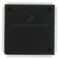
Manufacturer Part Number
MMC2107CFCAG33
Description
IC MCU 33MHZ 128K FLASH 144-LQFP
Manufacturer
Freescale Semiconductor
Series
MCorer
Datasheet
1.MMC2107CFCAF33.pdf
(618 pages)
Specifications of MMC2107CFCAG33
Core Processor
M210
Core Size
32-Bit
Speed
33MHz
Connectivity
EBI/EMI, SCI, SPI
Peripherals
POR, PWM, WDT
Number Of I /o
72
Program Memory Size
128KB (128K x 8)
Program Memory Type
FLASH
Ram Size
8K x 8
Voltage - Supply (vcc/vdd)
2.7 V ~ 3.6 V
Data Converters
A/D 8x10b
Oscillator Type
Internal
Operating Temperature
-40°C ~ 85°C
Package / Case
144-LQFP
Processor Series
MMC2107
Core
M-CORE
Data Bus Width
32 bit
Data Ram Size
8 KB
Interface Type
SCI/SPI
Maximum Clock Frequency
33 MHz
Number Of Programmable I/os
72
Number Of Timers
2
Operating Supply Voltage
0 V to 3.6 V
Maximum Operating Temperature
+ 85 C
Mounting Style
SMD/SMT
Minimum Operating Temperature
- 40 C
On-chip Adc
8-ch x 10-bit
Cpu Family
Mcore
Device Core
MCORE
Device Core Size
32b
Frequency (max)
33MHz
Total Internal Ram Size
8KB
# I/os (max)
72
Number Of Timers - General Purpose
2
Operating Supply Voltage (typ)
3.3/5V
Operating Supply Voltage (max)
3.6/5.5V
Operating Supply Voltage (min)
2.7/4.5V
Instruction Set Architecture
RISC
Operating Temp Range
-40C to 85C
Operating Temperature Classification
Industrial
Mounting
Surface Mount
Pin Count
144
Package Type
LQFP
Lead Free Status / RoHS Status
Lead free / RoHS Compliant
Eeprom Size
-
Lead Free Status / Rohs Status
Lead free / RoHS Compliant
Available stocks
Company
Part Number
Manufacturer
Quantity
Price
Company:

Part Number:
MMC2107CFCAG33
Manufacturer:
FREESCALE
Quantity:
210
Company:
Part Number:
MMC2107CFCAG33
Manufacturer:
freescaie
Quantity:
35
Company:
Part Number:
MMC2107CFCAG33
Manufacturer:
Freescale Semiconductor
Quantity:
10 000


21.13 Signal Descriptions
21.13.1 Debug Serial Input (TDI)
21.13.2 Debug Serial Clock (TCLK)
21.13.3 Debug Serial Output (TDO)
MMC2107 – Rev. 2.0
MOTOROLA
The OnCE pin interface is used to transfer OnCE instructions and data
to the OnCE control block. Depending on the particular resource being
accessed, the CPU may need to be placed in debug mode. For
resources outside of the CPU block and contained in the OnCE block,
the processor is not disturbed and may continue execution. If a
processor resource is required, the OnCE controller may assert a debug
request (DBGRQ) to the CPU. This causes the CPU to finish the
instruction being executed, save the instruction pipeline information,
enter debug mode, and wait for further commands. Asserting DBGRQ
causes the device to exit stop, doze, or wait mode.
Data and commands are provided to the OnCE controller through the
TDI pin. Data is latched on the rising edge of the TCLK serial clock. Data
is shifted into the OnCE serial port least significant bit (LSB) first.
The TCLK pin supplies the serial clock to the OnCE control block. The
serial clock provides pulses required to shift data and commands into
and out of the OnCE serial port. (Data is clocked into the OnCE on the
rising edge and is clocked out of the OnCE serial port on the falling
edge.) The debug serial clock frequency must be no greater than
50 percent of the processor clock frequency.
Serial data is read from the OnCE block through the TDO pin. Data is
always shifted out the OnCE serial port LSB first. Data is clocked out of
the OnCE serial port on the falling edge of TCLK. TDO is three-stateable
and is actively driven in the shift-IR and shift-DR controller states. TDO
changes on the falling edge of TCLK.
Freescale Semiconductor, Inc.
For More Information On This Product,
JTAG Test Access Port and OnCE
Go to: www.freescale.com
JTAG Test Access Port and OnCE
Signal Descriptions
Technical Data
555
Related parts for MMC2107CFCAG33
Image
Part Number
Description
Manufacturer
Datasheet
Request
R

Part Number:
Description:
Manufacturer:
Freescale Semiconductor, Inc
Datasheet:
Part Number:
Description:
Manufacturer:
Freescale Semiconductor, Inc
Datasheet:
Part Number:
Description:
Manufacturer:
Freescale Semiconductor, Inc
Datasheet:
Part Number:
Description:
Manufacturer:
Freescale Semiconductor, Inc
Datasheet:
Part Number:
Description:
Manufacturer:
Freescale Semiconductor, Inc
Datasheet:
Part Number:
Description:
Manufacturer:
Freescale Semiconductor, Inc
Datasheet:
Part Number:
Description:
Manufacturer:
Freescale Semiconductor, Inc
Datasheet:
Part Number:
Description:
Manufacturer:
Freescale Semiconductor, Inc
Datasheet:
Part Number:
Description:
Manufacturer:
Freescale Semiconductor, Inc
Datasheet:
Part Number:
Description:
Manufacturer:
Freescale Semiconductor, Inc
Datasheet:
Part Number:
Description:
Manufacturer:
Freescale Semiconductor, Inc
Datasheet:
Part Number:
Description:
Manufacturer:
Freescale Semiconductor, Inc
Datasheet:
Part Number:
Description:
Manufacturer:
Freescale Semiconductor, Inc
Datasheet:
Part Number:
Description:
Manufacturer:
Freescale Semiconductor, Inc
Datasheet:
Part Number:
Description:
Manufacturer:
Freescale Semiconductor, Inc
Datasheet: