DS80C390-QCR+ Maxim Integrated Products, DS80C390-QCR+ Datasheet - Page 42
DS80C390-QCR+
Manufacturer Part Number
DS80C390-QCR+
Description
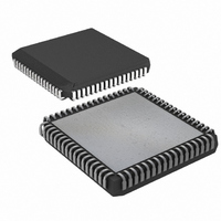
IC MPU CAN DUAL HS 68-PLCC
Manufacturer
Maxim Integrated Products
Series
80Cr
Datasheet
1.DS80C390-FCR.pdf
(53 pages)
Specifications of DS80C390-QCR+
Core Processor
8051
Core Size
8-Bit
Speed
40MHz
Connectivity
CAN, EBI/EMI, SIO, UART/USART
Peripherals
Power-Fail Reset, WDT
Number Of I /o
32
Program Memory Type
ROMless
Ram Size
4K x 8
Voltage - Supply (vcc/vdd)
3.85 V ~ 5.5 V
Oscillator Type
External
Operating Temperature
0°C ~ 70°C
Package / Case
68-LCC, 68-PLCC
Processor Series
DS80C390
Core
8051
Data Bus Width
8 bit
Program Memory Size
4 KB
Data Ram Size
4 KB
Interface Type
CAN, IrDA
Maximum Clock Frequency
40 MHz
Number Of Programmable I/os
32
Number Of Timers
3
Operating Supply Voltage
3.85 V to 5.5 V
Maximum Operating Temperature
+ 70 C
Mounting Style
SMD/SMT
3rd Party Development Tools
PK51, CA51, A51, ULINK2
Minimum Operating Temperature
0 C
Package
68PLCC
Device Core
8051
Family Name
80C
Maximum Speed
40 MHz
Lead Free Status / RoHS Status
Lead free / RoHS Compliant
Eeprom Size
-
Program Memory Size
-
Data Converters
-
Lead Free Status / Rohs Status
Details


TIMED-ACCESS PROTECTION
Selected SFR bits are critical to operation, making it desirable to protect them against an accidental write
operation. The timed-access procedure prevents an errant processor from accidentally altering bits that would
seriously affect processor operation. The timed-access procedure requires that the write of a protected bit be
immediately preceded by the following two instructions:
Writing an AAh followed by a 55h to the timed-access register (location C7h) opens a three-cycle window that
allows software to modify one of the protected bits. If the instruction that seeks to modify the protected bit is not
immediately preceded by these instructions, the write is ignored. The protected bits are:
WDCON.6
WDCON.3
WDCON.1
WDCON.0
RCON.0
ACON.2
ACON.1–0
MCON.7–6
MCON.5
MCON.3–0
C0C.3
C1C.3
P4CNT.6
P4CNT.5–0
P5CNT.2–0
COR.7
COR.6–5
COR.4–3
COR.2–1
COR.0
EMI REDUCTION
One of the major contributors to radiated noise in an 8051-based system is the toggling of ALE. The microcontroller
allows software to disable ALE when not used by setting the ALEOFF (PMR.2) bit to 1. When ALEOFF = 1, ALE
automatically toggles during an off-chip MOVX. However, ALE remains static when performing on-chip memory
access. The default state of ALEOFF is 0 so ALE normally toggles at a frequency of XTAL/4.
PERIPHERAL OVERVIEW
The DS80C390 provides several of the most commonly needed peripheral functions in microcomputer-based
systems. New functions include a second serial port, power-fail reset, power-fail interrupt flag, and a programmable
watchdog timer. In addition, the microcontroller contains two CAN modules for industrial communication
applications. Each of these peripherals is described in the following paragraphs. More details are available in the
High-Speed Microcontroller User’s Guide and the DS80C390 Supplement.
SERIAL PORTS
The microcontroller provides a serial port (UART) that is identical to the 80C52. In addition it includes a second
hardware serial port that is a full duplicate of the standard one. This second port optionally uses pins P1.2 (RXD1)
and P1.3 (TXD1). It has duplicate control functions included in new SFR locations. The second serial port can
alternately be mapped to P5.2 and P5.3 to allow use of both serial ports in nonmultiplexed mode.
Both ports can operate simultaneously but can be at different baud rates or even in different modes. The second
serial port has similar control registers (SCON1, SBUF1) to the original. The new serial port can only use Timer 1
for baud-rate generation.
MOV
MOV
0C7h, #0AAh
0C7h, #55h
POR
WDIF
EWT
RWT
BGS
SA
AM1–AM0
IDM1–IDM0
CMA
PDCE3–PDCE.0
CRST
CRST
SBCAN
P5.7–P5.5
IRDACK
C1BPR7–C1BPR6
C0BPR7–C0BPR6
COD1–COD0
CLKOE
42 of 53
Power-On Reset Flag
Watchdog Interrupt Flag
Watchdog Reset Enable
Reset Watchdog Timer
Bandgap Select
Stack Address Mode
Address Mode Select bits
Internal Memory Configuration and Location bits
CAN Data Memory Assignment
Program/Data Chip Enables
CAN 0 Reset
CAN 1 Reset
Single Bus CAN
Port 4 Pin Configuration Control Bits
Configuration Control Bits
IRDA Clock Output Enable
CAN 1 Baud Rate Prescale Bits
CAN 0 Baud Rate Prescale Bits
CAN Clock Output Divide Bit 1 and Bit 0
CAN Clock Output Enable
Related parts for DS80C390-QCR+
Image
Part Number
Description
Manufacturer
Datasheet
Request
R

Part Number:
Description:
Manufacturer:
Maxim Integrated Products
Datasheet:

Part Number:
Description:
IC MPU CAN DUAL HS 64-LQFP
Manufacturer:
Maxim Integrated Products
Datasheet:
Part Number:
Description:
IC MPU CAN DUAL HS IND 64-LQFP
Manufacturer:
Maxim Integrated Products
Datasheet:

Part Number:
Description:
IC MPU CAN DUAL HS 68-PLCC
Manufacturer:
Maxim Integrated Products
Datasheet:
Part Number:
Description:
IC MPU CAN DUAL HS IND 68-PLCC
Manufacturer:
Maxim Integrated Products
Datasheet:
Part Number:
Description:
IC MPU CAN DUAL HS IND 68-PLCC
Manufacturer:
Maxim Integrated Products
Datasheet:
Part Number:
Description:
IC MPU CAN DUAL HS 64-LQFP
Manufacturer:
Maxim Integrated Products
Datasheet:
Part Number:
Description:
IC MPU CAN DUAL HS IND 64-LQFP
Manufacturer:
Maxim Integrated Products
Datasheet:
Part Number:
Description:
MAX7528KCWPMaxim Integrated Products [CMOS Dual 8-Bit Buffered Multiplying DACs]
Manufacturer:
Maxim Integrated Products
Datasheet:
Part Number:
Description:
Single +5V, fully integrated, 1.25Gbps laser diode driver.
Manufacturer:
Maxim Integrated Products
Datasheet:
Part Number:
Description:
Single +5V, fully integrated, 155Mbps laser diode driver.
Manufacturer:
Maxim Integrated Products
Datasheet:
Part Number:
Description:
VRD11/VRD10, K8 Rev F 2/3/4-Phase PWM Controllers with Integrated Dual MOSFET Drivers
Manufacturer:
Maxim Integrated Products
Datasheet:
Part Number:
Description:
Highly Integrated Level 2 SMBus Battery Chargers
Manufacturer:
Maxim Integrated Products
Datasheet:
Part Number:
Description:
Current Monitor and Accumulator with Integrated Sense Resistor; ; Temperature Range: -40°C to +85°C
Manufacturer:
Maxim Integrated Products
Part Number:
Description:
TSSOP 14/A°/RS-485 Transceivers with Integrated 100O/120O Termination Resis
Manufacturer:
Maxim Integrated Products