DS80C390-QCR+ Maxim Integrated Products, DS80C390-QCR+ Datasheet - Page 34
DS80C390-QCR+
Manufacturer Part Number
DS80C390-QCR+
Description
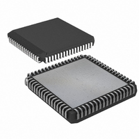
IC MPU CAN DUAL HS 68-PLCC
Manufacturer
Maxim Integrated Products
Series
80Cr
Datasheet
1.DS80C390-FCR.pdf
(53 pages)
Specifications of DS80C390-QCR+
Core Processor
8051
Core Size
8-Bit
Speed
40MHz
Connectivity
CAN, EBI/EMI, SIO, UART/USART
Peripherals
Power-Fail Reset, WDT
Number Of I /o
32
Program Memory Type
ROMless
Ram Size
4K x 8
Voltage - Supply (vcc/vdd)
3.85 V ~ 5.5 V
Oscillator Type
External
Operating Temperature
0°C ~ 70°C
Package / Case
68-LCC, 68-PLCC
Processor Series
DS80C390
Core
8051
Data Bus Width
8 bit
Program Memory Size
4 KB
Data Ram Size
4 KB
Interface Type
CAN, IrDA
Maximum Clock Frequency
40 MHz
Number Of Programmable I/os
32
Number Of Timers
3
Operating Supply Voltage
3.85 V to 5.5 V
Maximum Operating Temperature
+ 70 C
Mounting Style
SMD/SMT
3rd Party Development Tools
PK51, CA51, A51, ULINK2
Minimum Operating Temperature
0 C
Package
68PLCC
Device Core
8051
Family Name
80C
Maximum Speed
40 MHz
Lead Free Status / RoHS Status
Lead free / RoHS Compliant
Eeprom Size
-
Program Memory Size
-
Data Converters
-
Lead Free Status / Rohs Status
Details


40-BIT ACCUMULATOR
The accelerator also incorporates an automatic accumulator function, permitting the implementation of multiply-
and-accumulate and divide-and-accumulate functions without any additional delay. Each time the accelerator is
used for a multiply or divide operation, the result is transparently added to a 40-bit accumulator. This can greatly
increase speed of DSP and other high-level math operations.
The accumulator can be accessed anytime the multiply/accumulate status flag (MCNT1;D2h) is cleared. The
accumulator is initialized by performing five writes to the multiplier C register (MC;D5h), LSB first. The 40-bit
accumulator can be read by performing five reads of the multiplier C register, MSB first.
MEMORY ADDRESSING
The DS80C390 incorporates three internal memory areas:
Up to 4MB of external memory is addressed via a multiplexed or demultiplexed 20-bit address bus/8-bit data bus
and four chip-enable (active during program memory access) or four peripheral-enable (active during data memory
access) signals. Three different addressing modes are supported, as selected by the AM1, AM0 bits in the ACON
SFR.
16-Bit Address Mode
Memory is accessed by 16-bit address mode similarly to the traditional 8051. It is op-code compatible with the 8051
microprocessor and identical to the byte and cycle count of the Dallas Semiconductor High-Speed Microcontroller
family. A device operating in this mode can access up to 64kB of program and data memory. The device defaults to
this mode following any reset.
22-Bit Paged-Address Mode
The 22-bit paged-address mode retains binary-code compatibility with the 8051 instruction set, but adds one
machine cycle to the ACALL, LCALL, RET, and RETI instructions with respect to Dallas Semiconductor’s High-
Speed Microcontroller family timing. This is transparent to standard 8051 compilers. Interrupt latency is also
increased by one machine cycle. In this mode, interrupt vectors are fetched from 0000xxh.
22-Bit Contiguous Address Mode
The 22-bit contiguous addressing mode uses a full 22-bit program counter, and all modified branching instructions
automatically save and restore the entire program counter. The 22-bit branching instructions such as ACALL,
AJMP, LCALL, LJMP, MOV DPTR, RET, and RETI instructions require an assembler, compiler, and linker that
specifically supports these features. The INC DPTR is lengthened by one cycle but remains byte-count-compatible
with the standard 8051 instruction set.
Internally, the device uses a 22-bit program counter. The lowest order 22 bits are used for memory addressing,
with a special 23rd bit used to map the 4kB SRAM above the 4MB memory space in bootstrap loader applications.
Address bits 16–23 for the 22-bit addressing modes are generated through additional SFRs dependent on the type
of instruction as shown in
Table 4. Extended Address Generation
MOVX instructions using DPTR
MOVX instructions using DPTR1
MOVX instructions using @Ri
Addressing program memory in 22-bit
paged mode
10-bit stack pointer mode
256 bytes of scratchpad (or direct) RAM
4kB of SRAM configurable as various combinations of MOVX data memory, stack memory, and MOVC
program memory
512 bytes of RAM reserved for the CAN message centers.
INSTRUCTION
Table
4.
ADDRESS BITS
MXAX;EAh
DPX1;95h
DPX;93h
AP;9Ch
23–16
—
34 of 53
ADDRESS BITS
DPH1;85h
DPH;83h
ESP;9Bh
P2;A0h
15–8
—
ADDRESS BITS
DPL1;84h
DPL;82h
SP;81h
7–0
—
Ri
Related parts for DS80C390-QCR+
Image
Part Number
Description
Manufacturer
Datasheet
Request
R

Part Number:
Description:
Manufacturer:
Maxim Integrated Products
Datasheet:

Part Number:
Description:
IC MPU CAN DUAL HS 64-LQFP
Manufacturer:
Maxim Integrated Products
Datasheet:
Part Number:
Description:
IC MPU CAN DUAL HS IND 64-LQFP
Manufacturer:
Maxim Integrated Products
Datasheet:

Part Number:
Description:
IC MPU CAN DUAL HS 68-PLCC
Manufacturer:
Maxim Integrated Products
Datasheet:
Part Number:
Description:
IC MPU CAN DUAL HS IND 68-PLCC
Manufacturer:
Maxim Integrated Products
Datasheet:
Part Number:
Description:
IC MPU CAN DUAL HS IND 68-PLCC
Manufacturer:
Maxim Integrated Products
Datasheet:
Part Number:
Description:
IC MPU CAN DUAL HS 64-LQFP
Manufacturer:
Maxim Integrated Products
Datasheet:
Part Number:
Description:
IC MPU CAN DUAL HS IND 64-LQFP
Manufacturer:
Maxim Integrated Products
Datasheet:
Part Number:
Description:
MAX7528KCWPMaxim Integrated Products [CMOS Dual 8-Bit Buffered Multiplying DACs]
Manufacturer:
Maxim Integrated Products
Datasheet:
Part Number:
Description:
Single +5V, fully integrated, 1.25Gbps laser diode driver.
Manufacturer:
Maxim Integrated Products
Datasheet:
Part Number:
Description:
Single +5V, fully integrated, 155Mbps laser diode driver.
Manufacturer:
Maxim Integrated Products
Datasheet:
Part Number:
Description:
VRD11/VRD10, K8 Rev F 2/3/4-Phase PWM Controllers with Integrated Dual MOSFET Drivers
Manufacturer:
Maxim Integrated Products
Datasheet:
Part Number:
Description:
Highly Integrated Level 2 SMBus Battery Chargers
Manufacturer:
Maxim Integrated Products
Datasheet:
Part Number:
Description:
Current Monitor and Accumulator with Integrated Sense Resistor; ; Temperature Range: -40°C to +85°C
Manufacturer:
Maxim Integrated Products
Part Number:
Description:
TSSOP 14/A°/RS-485 Transceivers with Integrated 100O/120O Termination Resis
Manufacturer:
Maxim Integrated Products