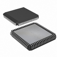
DS80C390-QCR+ Maxim Integrated Products, DS80C390-QCR+ Datasheet - Page 37

DS80C390-QCR+
Manufacturer Part Number
DS80C390-QCR+
Description
IC MPU CAN DUAL HS 68-PLCC
Manufacturer
Maxim Integrated Products
Series
80Cr
Datasheet
1.DS80C390-FCR.pdf
(53 pages)
Specifications of DS80C390-QCR+
Core Processor
8051
Core Size
8-Bit
Speed
40MHz
Connectivity
CAN, EBI/EMI, SIO, UART/USART
Peripherals
Power-Fail Reset, WDT
Number Of I /o
32
Program Memory Type
ROMless
Ram Size
4K x 8
Voltage - Supply (vcc/vdd)
3.85 V ~ 5.5 V
Oscillator Type
External
Operating Temperature
0°C ~ 70°C
Package / Case
68-LCC, 68-PLCC
Processor Series
DS80C390
Core
8051
Data Bus Width
8 bit
Program Memory Size
4 KB
Data Ram Size
4 KB
Interface Type
CAN, IrDA
Maximum Clock Frequency
40 MHz
Number Of Programmable I/os
32
Number Of Timers
3
Operating Supply Voltage
3.85 V to 5.5 V
Maximum Operating Temperature
+ 70 C
Mounting Style
SMD/SMT
3rd Party Development Tools
PK51, CA51, A51, ULINK2
Minimum Operating Temperature
0 C
Package
68PLCC
Device Core
8051
Family Name
80C
Maximum Speed
40 MHz
Lead Free Status / RoHS Status
Lead free / RoHS Compliant
Eeprom Size
-
Program Memory Size
-
Data Converters
-
Lead Free Status / Rohs Status
Details
Table 9. Data Memory Cycle Stretch Values
*All internal MOVX operations execute at the 0 Stretch setting.
**Default stretch setting for external MOVX operations following reset.
EXTENDED STACK POINTER
The DS80C390 supports both the traditional 8-bit and an extended 10-bit stack pointer that improves the
performance of large programs written in high-level languages such as C. Enable the 10-bit stack pointer feature by
setting the stack address mode bit, SA (ACON.2). The bit is cleared following a reset, forcing the device to use an
8-bit stack located in the scratchpad RAM area. When the SA bit is set, the device will address up to 1kB of stack
memory in the first 1kB of the internal MOVX memory. The 10-bit stack pointer address is generated by
concatenating the lower two bits of the extended stack pointer (ESP;9Bh) and the traditional 8051 stack pointer
(SP;81h). The 10-bit stack pointer cannot be enabled when the 4kB of SRAM is mapped as both program and data
memory.
ENHANCED DUAL DATA POINTERS
The DS80C390 contains two data pointers, DPTR0 and DPTR1, designed to improve performance in applications
that require high data throughput. Incorporating a second data pointer allows the software to greatly speed up block
data (MOVX) moves by using one data pointer as a source register and the other as the destination register.
DPTR0 is located at the same address as the original 8051 data pointer, allowing the DS80C390 to execute
standard 8051 code with no modifications. The second data pointer, DPTR1, is split between the DPH1 and DPL1
SFRs, similar to the DPTR0 configuration. The active data pointer is selected with the data pointer select bit SEL
(DPS.0). Any instructions that reference the DPTR (i.e., MOVX A, @DPTR), will select DPTR0 if SEL = 0, and
DPTR1 if SEL = 1. Because the bits adjacent to SEL are not implemented, the state of SEL (and thus the active
data pointer) can be quickly toggled by the INC DPS instruction without disturbing other bits in the DPS register.
Unlike the standard 8051, the DS80C390 has the ability to decrement as well as increment the data pointers
without additional instructions. When the INC DPTR instruction is executed, the active DPTR increments or
decrements according to the ID1, ID0 (DPS.7-6), and SEL (DPS.0) bits as shown. The inactive DPTR is not
affected.
Table 10. Data Pointer Auto Increment/
Decrement Configuration
Another useful feature of the device is its ability to automatically switch the active data pointer after a DPTR-based
instruction is executed. This feature can greatly reduce the software overhead associated with data memory block
moves, which toggle between the source and destination registers. When the toggle-select bit (TSL;DPS.5) is set
to 1, the SEL bit (DPS.0) is automatically toggled every time one of the following DPTR-related instructions is
executed.
MD2
ID1
X
X
0
0
0
0
1
1
1
1
0
1
MD1
ID0
0
0
1
1
0
0
1
1
X
X
0
1
MD0
SEL
0
1
0
1
0
1
0
1
0
0
1
1
STRETCH
COUNT
CYCLE
INC DPTR RESULT
Decrement DPTR0
Decrement DPTR1
Increment DPTR0
Increment DPTR1
1**
0*
2
3
4
5
6
7
MACHINE
CYCLES
MOVX
10
11
12
2
3
4
5
9
37 of 53
CD1:0 = 00)
(4X/2X = 1
0.5 t
2 t
3 t
4 t
5 t
6 t
7 t
t
t
CLCL
MCS
RD, WR PULSE WIDTH (IN OSCILLATOR CLOCKS)
CLCL
CLCL
CLCL
CLCL
CLCL
CLCL
CLCL
CD1:0 = 00)
(4X/2X = 0
10 t
12 t
14 t
1 t
2 t
4 t
6 t
8 t
t
MCS
CLCL
CLCL
CLCL
CLCL
CLCL
CLCL
CLCL
CLCL
CD1:0 = 10)
(4X/2X = X
12 t
16 t
20 t
24 t
28 t
2 t
4 t
8 t
t
MCS
CLCL
CLCL
CLCL
CLCL
CLCL
CLCL
CLCL
CLCL
CD1:0 = 11)
12,288 t
16,384 t
20,480 t
24,576 t
28,672 t
(4X/2X = X
2048 t
4096 t
8192 t
t
MCS
CLCL
CLCL
CLCL
CLCL
CLCL
CLCL
CLCL
CLCL


