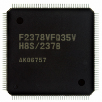
DF2378BVFQ35WV Renesas Electronics America, DF2378BVFQ35WV Datasheet - Page 63

DF2378BVFQ35WV
Manufacturer Part Number
DF2378BVFQ35WV
Description
IC H8S/2378 MCU FLASH 144-QFP
Manufacturer
Renesas Electronics America
Series
H8® H8S/2300r
Datasheet
1.YR0K42378FC000BA.pdf
(1208 pages)
Specifications of DF2378BVFQ35WV
Core Processor
H8S/2000
Core Size
16-Bit
Speed
35MHz
Connectivity
I²C, IrDA, SCI, SmartCard
Peripherals
DMA, POR, PWM, WDT
Number Of I /o
97
Program Memory Size
512KB (512K x 8)
Program Memory Type
FLASH
Ram Size
32K x 8
Voltage - Supply (vcc/vdd)
3 V ~ 3.6 V
Data Converters
A/D 16x10b; D/A 6x8b
Oscillator Type
Internal
Operating Temperature
-40°C ~ 85°C
Package / Case
144-QFP
For Use With
EDK2378 - DEV EVAL KIT FOR H8S/2378
Lead Free Status / RoHS Status
Lead free / RoHS Compliant
Eeprom Size
-
Available stocks
Company
Part Number
Manufacturer
Quantity
Price
Company:
Part Number:
DF2378BVFQ35WV
Manufacturer:
Renesas Electronics America
Quantity:
10 000
- Current page: 63 of 1208
- Download datasheet (8Mb)
Table 9.6
Table 9.7
Table 9.8
Section 10 I/O Ports ...........................................................................................455
Table 10.1
Table 10.2
Table 10.3
Table 10.4
Table 10.5
Table 10.6
Section 11 16-Bit Timer Pulse Unit (TPU)........................................................545
Table 11.1
Table 11.2
Table 11.3
Table 11.4
Table 11.5
Table 11.6
Table 11.7
Table 11.8
Table 11.9
Table 11.10 TPSC2 to TPSC0 (Channel 5)................................................................................. 556
Table 11.11 MD3 to MD0........................................................................................................... 558
Table 11.12 TIORH_0................................................................................................................. 560
Table 11.13 TIORL_0 ................................................................................................................. 561
Table 11.14 TIOR_1 ................................................................................................................... 562
Table 11.15 TIOR_2 ................................................................................................................... 563
Table 11.16 TIORH_3................................................................................................................. 564
Table 11.17 TIORL_3 ................................................................................................................. 565
Table 11.18 TIOR_4 ................................................................................................................... 566
Table 11.19 TIOR_5 ................................................................................................................... 567
Table 11.20 TIORH_0................................................................................................................. 568
Table 11.21 TIORL_0 ................................................................................................................. 569
Table 11.22 TIOR_1 ................................................................................................................... 570
Table 11.23 TIOR_2 ................................................................................................................... 571
Table 11.24 TIORH_3................................................................................................................. 572
Table 11.25 TIORL_3 ................................................................................................................. 573
Table 11.26 TIOR_4 ................................................................................................................... 574
Table 11.27 TIOR_5 ................................................................................................................... 575
Table 11.28 Register Combinations in Buffer Operation............................................................ 592
Register Function in Block Transfer Mode ............................................................. 442
DTC Execution Status ............................................................................................. 446
Number of States Required for Each Execution Status ........................................... 446
Port Functions ......................................................................................................... 456
Input Pull-Up MOS States (Port A)......................................................................... 512
Input Pull-Up MOS States (Port B)......................................................................... 516
Input Pull-Up MOS States (Port C)........................................................................ 520
Input Pull-Up MOS States (Port D)......................................................................... 524
Input Pull-Up MOS States (Port E) ......................................................................... 528
TPU Functions......................................................................................................... 546
Pin Configuration .................................................................................................... 549
CCLR2 to CCLR0 (Channels 0 and 3).................................................................... 553
CCLR2 to CCLR0 (Channels 1, 2, 4, and 5)........................................................... 553
TPSC2 to TPSC0 (Channel 0)................................................................................. 554
TPSC2 to TPSC0 (Channel 1)................................................................................. 554
TPSC2 to TPSC0 (Channel 2)................................................................................. 555
TPSC2 to TPSC0 (Channel 3)................................................................................. 555
TPSC2 to TPSC0 (Channel 4)................................................................................. 556
Rev.7.00 Mar. 18, 2009 page lxi of lxvi
REJ09B0109-0700
Related parts for DF2378BVFQ35WV
Image
Part Number
Description
Manufacturer
Datasheet
Request
R

Part Number:
Description:
KIT STARTER FOR M16C/29
Manufacturer:
Renesas Electronics America
Datasheet:

Part Number:
Description:
KIT STARTER FOR R8C/2D
Manufacturer:
Renesas Electronics America
Datasheet:

Part Number:
Description:
R0K33062P STARTER KIT
Manufacturer:
Renesas Electronics America
Datasheet:

Part Number:
Description:
KIT STARTER FOR R8C/23 E8A
Manufacturer:
Renesas Electronics America
Datasheet:

Part Number:
Description:
KIT STARTER FOR R8C/25
Manufacturer:
Renesas Electronics America
Datasheet:

Part Number:
Description:
KIT STARTER H8S2456 SHARPE DSPLY
Manufacturer:
Renesas Electronics America
Datasheet:

Part Number:
Description:
KIT STARTER FOR R8C38C
Manufacturer:
Renesas Electronics America
Datasheet:

Part Number:
Description:
KIT STARTER FOR R8C35C
Manufacturer:
Renesas Electronics America
Datasheet:

Part Number:
Description:
KIT STARTER FOR R8CL3AC+LCD APPS
Manufacturer:
Renesas Electronics America
Datasheet:

Part Number:
Description:
KIT STARTER FOR RX610
Manufacturer:
Renesas Electronics America
Datasheet:

Part Number:
Description:
KIT STARTER FOR R32C/118
Manufacturer:
Renesas Electronics America
Datasheet:

Part Number:
Description:
KIT DEV RSK-R8C/26-29
Manufacturer:
Renesas Electronics America
Datasheet:

Part Number:
Description:
KIT STARTER FOR SH7124
Manufacturer:
Renesas Electronics America
Datasheet:

Part Number:
Description:
KIT STARTER FOR H8SX/1622
Manufacturer:
Renesas Electronics America
Datasheet:

Part Number:
Description:
KIT DEV FOR SH7203
Manufacturer:
Renesas Electronics America
Datasheet:


