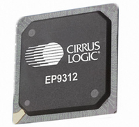
EP9312-IBZ Cirrus Logic Inc, EP9312-IBZ Datasheet - Page 480

EP9312-IBZ
Manufacturer Part Number
EP9312-IBZ
Description
IC ARM920T MCU 200MHZ 352-PBGA
Manufacturer
Cirrus Logic Inc
Series
EP9r
Specifications of EP9312-IBZ
Core Size
16/32-Bit
Package / Case
352-BGA
Core Processor
ARM9
Speed
200MHz
Connectivity
EBI/EMI, EIDE, Ethernet, I²C, IrDA, Keypad/Touchscreen, SPI, UART/USART, USB
Peripherals
AC'97, DMA, I²:S, LCD, LED, MaverickKey, POR, PWM, WDT
Number Of I /o
16
Program Memory Type
ROMless
Ram Size
32K x 8
Voltage - Supply (vcc/vdd)
1.65 V ~ 3.6 V
Data Converters
A/D 8x12b
Oscillator Type
External
Operating Temperature
-40°C ~ 85°C
Controller Family/series
(ARM9)
A/d Converter
12 Bits
No. Of I/o Pins
65
Clock Frequency
200MHz
Processor Series
EP93xx
Core
ARM920T
Data Bus Width
32 bit
3rd Party Development Tools
MDK-ARM, RL-ARM, ULINK2
Lead Free Status / RoHS Status
Lead free / RoHS Compliant
Eeprom Size
-
Program Memory Size
-
Lead Free Status / Rohs Status
Details
Other names
598-1260
Available stocks
Company
Part Number
Manufacturer
Quantity
Price
Company:
Part Number:
EP9312-IBZ
Manufacturer:
CIRRUS
Quantity:
30
Company:
Part Number:
EP9312-IBZ
Manufacturer:
HITTITE
Quantity:
1 200
- Current page: 480 of 824
- Download datasheet (13Mb)
12
12-2
Static Memory Controller
EP93xx User’s Guide
12.2 Static Memory Controller Operation
The SMC has five main functions:
The SMC provides access to static memory devices that are attached to the external bus.
The SMC can work with a wide variety of external device types, including SRAM, ROM, NOR
FLASH, and peripherals that respond to SRAM-type signaling.
Six chip-select output signals, CSn7, CSn6, CSn3, CSn2,
access six different memory spaces. However, only one of the six memory banks can be
accessed at a given time. The SMC has six independent control registers that configure the
six respective chip-select signals. Each control register,
characteristics that are needed to access the memory device(s) in its respective memory
space.
As shown in
that occurs just prior to the HCLK edge that de-asserts the chip-select output signal on the
CSnX pin. The output signal on the CSnX pin and the address outputs on the AD[x] pins are
de-asserted on the next HCLK edge.
The SMC can insert wait cycles into its access timing. Wait cycles can be specified by:
1. Memory bank selecting
2. Access timing
3. Wait State generation
4. Byte lane write enabling
5. External bus interfacing
• A programmable value, N, where N has the range 1<N<32. When N is used, the SMC
• An asserted wait input signal on the WAITn pin. As shown in
• When both N and
holds its bus state for N HCLK cycles. The value for N must be written to the WST2
and/or WST1 fields of the
4, the WAITn pin can be asserted as needed by an external device to extend access
time. When WAITn is asserted, the SMC holds its bus state until WAITn is sampled as
being de-asserted. For internal synchronization to occur,
for a minimum of two HCLK cycles.
until WAITn is sampled as being de-asserted, whichever occurs last.
Figure 12-1
WAITn
and
Figure
are used, the SMC holds its bus state for N HCLK cycles or
Copyright 2007 Cirrus Logic
"SMCBCR[7:0]"
12-3, the SMC captures read data on the HCLK edge
register(s).
"SMCBCR[7:0]"
CSn1, and
WAITn
Figure 12-3
CSn0 can be used to
must remain asserted
specifies the timing
and
Figure 12-
DS785UM1
Related parts for EP9312-IBZ
Image
Part Number
Description
Manufacturer
Datasheet
Request
R

Part Number:
Description:
IC ARM9 SOC UNIVERSAL 352PBGA
Manufacturer:
Cirrus Logic Inc
Datasheet:

Part Number:
Description:
System-on-Chip Processor
Manufacturer:
Cirrus Logic Inc
Datasheet:

Part Number:
Description:
IC ARM920T MCU 200MHZ 352-PBGA
Manufacturer:
Cirrus Logic Inc
Datasheet:

Part Number:
Description:
Development Kit
Manufacturer:
Cirrus Logic Inc
Datasheet:

Part Number:
Description:
Development Kit
Manufacturer:
Cirrus Logic Inc
Datasheet:

Part Number:
Description:
High-efficiency PFC + Fluorescent Lamp Driver Reference Design
Manufacturer:
Cirrus Logic Inc
Datasheet:

Part Number:
Description:
Development Kit
Manufacturer:
Cirrus Logic Inc
Datasheet:

Part Number:
Description:
Development Kit
Manufacturer:
Cirrus Logic Inc
Datasheet:

Part Number:
Description:
Development Kit
Manufacturer:
Cirrus Logic Inc
Datasheet:

Part Number:
Description:
Development Kit
Manufacturer:
Cirrus Logic Inc
Datasheet:

Part Number:
Description:
Development Kit
Manufacturer:
Cirrus Logic Inc
Datasheet:

Part Number:
Description:
Development Kit
Manufacturer:
Cirrus Logic Inc
Datasheet:

Part Number:
Description:
Ref Bd For Speakerbar MSA & DSP Products
Manufacturer:
Cirrus Logic Inc


