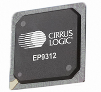
EP9312-IBZ Cirrus Logic Inc, EP9312-IBZ Datasheet - Page 15

EP9312-IBZ
Manufacturer Part Number
EP9312-IBZ
Description
IC ARM920T MCU 200MHZ 352-PBGA
Manufacturer
Cirrus Logic Inc
Series
EP9r
Specifications of EP9312-IBZ
Core Size
16/32-Bit
Package / Case
352-BGA
Core Processor
ARM9
Speed
200MHz
Connectivity
EBI/EMI, EIDE, Ethernet, I²C, IrDA, Keypad/Touchscreen, SPI, UART/USART, USB
Peripherals
AC'97, DMA, I²:S, LCD, LED, MaverickKey, POR, PWM, WDT
Number Of I /o
16
Program Memory Type
ROMless
Ram Size
32K x 8
Voltage - Supply (vcc/vdd)
1.65 V ~ 3.6 V
Data Converters
A/D 8x12b
Oscillator Type
External
Operating Temperature
-40°C ~ 85°C
Controller Family/series
(ARM9)
A/d Converter
12 Bits
No. Of I/o Pins
65
Clock Frequency
200MHz
Processor Series
EP93xx
Core
ARM920T
Data Bus Width
32 bit
3rd Party Development Tools
MDK-ARM, RL-ARM, ULINK2
Lead Free Status / RoHS Status
Lead free / RoHS Compliant
Eeprom Size
-
Program Memory Size
-
Lead Free Status / Rohs Status
Details
Other names
598-1260
Available stocks
Company
Part Number
Manufacturer
Quantity
Price
Company:
Part Number:
EP9312-IBZ
Manufacturer:
CIRRUS
Quantity:
30
Company:
Part Number:
EP9312-IBZ
Manufacturer:
HITTITE
Quantity:
1 200
- Current page: 15 of 824
- Download datasheet (13Mb)
EP93xx User’s Guide
Figure 4-1. Flow Chart of Boot ROM Software..............................................................................................4-4
Figure 4-2. Flow chart of Boot Sequence for 16-bit SDRAM Devices ...........................................................4-7
Figure 5-1. Phase Locked Loop (PLL) Structure ...........................................................................................5-4
Figure 5-2. Clock Generation System ...........................................................................................................5-6
Figure 5-3. Bus Clock Generation .................................................................................................................5-7
Figure 5-4. Power States and Transitions ...................................................................................................5-11
Figure 6-1. Vectored Interrupt Controller Block Diagram ..............................................................................6-2
Figure 7-1. Raster Engine Block Diagram .....................................................................................................7-8
Figure 7-2. Video Buffer Diagram..................................................................................................................7-9
Figure 7-3. Graphics Matrix for 50% Duty Cycle .........................................................................................7-20
Figure 7-4. Sample Matrix Causing Flickering ............................................................................................7-21
Figure 7-5.. Sample Matrix That Avoids Flickering......................................................................................7-21
Figure 7-6. Programming for One-third Luminous Intensity ........................................................................7-22
Figure 7-7. Creating Bit Patterns that Move to the Right.............................................................................7-23
Figure 7-8. Three and Four Count Axis .......................................................................................................7-24
Figure 7-9. Progressive/Dual Scan Video Signals ......................................................................................7-29
Figure 7-10. Interlaced Video Signals .........................................................................................................7-30
Figure 9-1. 1/10/100 Mbps Ethernet LAN Controller Block Diagram.............................................................9-1
Figure 9-2. Ethernet Frame / Packet Format (Type II only)...........................................................................9-4
Figure 9-3. Packet Transmission Process.....................................................................................................9-5
Figure 9-4. Carrier Deference State Diagram ...............................................................................................9-6
Figure 9-5. Data Bit Transmission Order.......................................................................................................9-8
Figure 9-6. CRC Logic...................................................................................................................................9-9
Figure 9-7. Receive Descriptor Format and Data Fragments .....................................................................9-14
Figure 9-8. Receive Status Queue ..............................................................................................................9-17
Figure 9-9. Receive Flow Diagram ............................................................................................................9-21
Figure 9-10. Receive Descriptor Data/Status Flow .....................................................................................9-23
Figure 9-11. Receive Descriptor Example...................................................................................................9-24
Figure 9-12. Receive Frame Pre-processing ..............................................................................................9-25
Figure 9-13. Transmit Descriptor Format and Data Fragments ..................................................................9-27
Figure 9-14. Multiple Fragments Per Transmit Frame ................................................................................9-28
Figure 9-15. Transmit Status Queue ...........................................................................................................9-31
Figure 9-16. Transmit Flow Diagram ...........................................................................................................9-34
Figure 9-17. Transmit Descriptor Data/Status Flow ....................................................................................9-36
Figure 10-1. DMA M2P/P2M Finite State Machine .....................................................................................10-7
Figure 10-2. M2M DMA Control Finite State Machine...............................................................................10-10
Figure 10-3. M2M DMA Buffer Finite State Machine.................................................................................10-12
©
DS785UM1
Copyright 2007 Cirrus Logic, Inc.
xv
Related parts for EP9312-IBZ
Image
Part Number
Description
Manufacturer
Datasheet
Request
R

Part Number:
Description:
IC ARM9 SOC UNIVERSAL 352PBGA
Manufacturer:
Cirrus Logic Inc
Datasheet:

Part Number:
Description:
System-on-Chip Processor
Manufacturer:
Cirrus Logic Inc
Datasheet:

Part Number:
Description:
IC ARM920T MCU 200MHZ 352-PBGA
Manufacturer:
Cirrus Logic Inc
Datasheet:

Part Number:
Description:
Development Kit
Manufacturer:
Cirrus Logic Inc
Datasheet:

Part Number:
Description:
Development Kit
Manufacturer:
Cirrus Logic Inc
Datasheet:

Part Number:
Description:
High-efficiency PFC + Fluorescent Lamp Driver Reference Design
Manufacturer:
Cirrus Logic Inc
Datasheet:

Part Number:
Description:
Development Kit
Manufacturer:
Cirrus Logic Inc
Datasheet:

Part Number:
Description:
Development Kit
Manufacturer:
Cirrus Logic Inc
Datasheet:

Part Number:
Description:
Development Kit
Manufacturer:
Cirrus Logic Inc
Datasheet:

Part Number:
Description:
Development Kit
Manufacturer:
Cirrus Logic Inc
Datasheet:

Part Number:
Description:
Development Kit
Manufacturer:
Cirrus Logic Inc
Datasheet:

Part Number:
Description:
Development Kit
Manufacturer:
Cirrus Logic Inc
Datasheet:

Part Number:
Description:
Ref Bd For Speakerbar MSA & DSP Products
Manufacturer:
Cirrus Logic Inc


