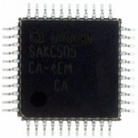
SAK-C505CA-4EM CA Infineon Technologies, SAK-C505CA-4EM CA Datasheet - Page 64

SAK-C505CA-4EM CA
Manufacturer Part Number
SAK-C505CA-4EM CA
Description
IC MCU 8BIT 32KB OTP MQFP-44-2
Manufacturer
Infineon Technologies
Series
C5xx/C8xxr
Datasheet
1.SAK-C505CA-4EM_CA.pdf
(88 pages)
Specifications of SAK-C505CA-4EM CA
Core Processor
C500
Core Size
8-Bit
Speed
20MHz
Connectivity
CAN, EBI/EMI, UART/USART
Peripherals
POR, PWM, WDT
Number Of I /o
34
Program Memory Size
32KB (32K x 8)
Program Memory Type
OTP
Ram Size
1.25K x 8
Voltage - Supply (vcc/vdd)
4.25 V ~ 5.5 V
Data Converters
A/D 8x10b
Oscillator Type
External
Operating Temperature
-40°C ~ 125°C
Package / Case
44-BQFP
Data Bus Width
8 bit
Data Ram Size
1.25 KB
Interface Type
CAN, USART
Maximum Clock Frequency
20 MHz
Number Of Programmable I/os
34
Number Of Timers
3
Maximum Operating Temperature
+ 125 C
Mounting Style
SMD/SMT
Minimum Operating Temperature
- 40 C
On-chip Adc
10 bit, 8 Channel
Packages
PG-MQFP-44
Max Clock Frequency
20.0 MHz
Sram (incl. Cache)
1.25 KByte
Can Nodes
1
A / D Input Lines (incl. Fadc)
8
Program Memory
32.0 KByte
Lead Free Status / RoHS Status
Lead free / RoHS Compliant
Eeprom Size
-
Lead Free Status / Rohs Status
Details
Other names
K505CA4EMCANP
K505CA4EMCAXT
SAK-C505CA-4EMCA
SAK-C505CA-4EMCAINTR
SAK-C505CA-4EMCATR
SAK-C505CA-4EMCATR
SAKC505CA4EMCAXT
SP000106397
K505CA4EMCAXT
SAK-C505CA-4EMCA
SAK-C505CA-4EMCAINTR
SAK-C505CA-4EMCATR
SAK-C505CA-4EMCATR
SAKC505CA4EMCAXT
SP000106397
Note:
1) Capacitive loading on ports 0 and 2 may cause spurious noise pulses to be superimposed on the
2) Capacitive loading on ports 0 and 2 may cause the
3) Overload conditions under operating conditions occur if the voltage on the respective pin exceeds the specified
4) Not 100% tested, guaranteed by design characterization.
5) Only valid for C505A-4E and C505CA-4E.
6) Only valid for C505A-4E and C505CA-4E in programming mode.
7)
8)
9)
10)
11)
12) The typical
13) The maximum
14) The values are valid for C505CA-4R, C505CA-2R, C505CA-L, C505A-4R, C505A-2R and C505A-L only.
Data Sheet
and port 3. The noise is due to external bus capacitance discharging into the port 0 and port 2 pins when these
pins make 1-to-0 transitions during bus operation. In the worst case (capacitive loading > 100 pF), the noise
pulse on ALE line may exceed 0.8 V. In such cases it may be desirable to qualify ALE with a schmitt-trigger,
or use an address latch with a schmitt-trigger strobe input.
0.9
operating range (i.e.
pins may not exceed 50 mA. The supply voltage
I
XTAL1 driven with
EA = Port 0 = RESET =
I
XTAL1 driven with
RESET = EA =
software;
I
disabled;
XTAL1 driven with
RESET = EA =
software;
I
disabled;
XTAL1 driven with
RESET = EA =
with slow-down enabled by software;
I
Port 0 = EA =
all other pins are disconnected.
PD
DD
DD
DD
DD
V
(power-down mode) is measured under following conditions:
(active mode) is measured with:
(idle mode) is measured with all output pins disconnected and with all peripherals disabled;
(active mode with slow-down mode) is measured with all output pins disconnected and with all peripherals
(idle mode with slow-down mode) is measured with all output pins disconnected and with all peripherals
DD
specification when the address lines are stabilizing.
I
DD
V
I
values are periodically measured at
V
V
DD
V
DD
SS
SS
SS
values are measured under worst case conditions (
; RESET =
t
t
t
t
R
R
R
R
; Port0 =
; Port0 =
; all other pins are disconnected; the microcontroller is put into slow-down mode by
V
,
,
,
,
OV
t
t
t
t
F
F
F
F
V
>
= 5 ns, 50% duty cycle ,
= 5 ns, 50% duty cycle,
= 5 ns, 50% duty cycle,
= 5 ns, 50% duty cycle,
DD
V
; all other pins are disconnected.
DD
V
V
V
DD
DD
SS
+ 0.5 V or
; all other pins are disconnected; the microcontroller is put into idle mode by
; XTAL2 = N.C.; XTAL1 =
; all other pins are disconnected; the microcontroller is put into idle mode
V
OV
<
V
V
V
V
V
V
DD
SS
IL
IL
IL
60
IL
T
=
=
=
and
- 0.5 V). The absolute sum of input currents on all port
=
A
V
V
V
V
OH
= +25 °C but not 100% tested.
V
SS
SS
SS
SS
V
on ALE and PSEN to momentarily fall below the
SS
+ 0.5 V,
+ 0.5 V,
+ 0.5 V,
+ 0.5 V,
V
must remain within the specified limits.
SS
;
C505/C505C/C505A/C505CA
V
V
V
V
AGND
V
IH
IH
IH
IH
T
=
=
=
=
A
=
V
V
V
V
= 0 °C or -40 °C and
V
DD
DD
DD
DD
SS
– 0.5 V; XTAL2 = N.C.;
– 0.5 V; XTAL2 = N.C.;
– 0.5 V; XTAL2 = N.C.;
– 0.5 V; XTAL2 = N.C.;
;
V
AREF
=
V
DD
;
V
DD
V
OL
= 5.5 V)
of ALE
12.00


