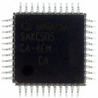
SAK-C505CA-4EM CA Infineon Technologies, SAK-C505CA-4EM CA Datasheet - Page 46

SAK-C505CA-4EM CA
Manufacturer Part Number
SAK-C505CA-4EM CA
Description
IC MCU 8BIT 32KB OTP MQFP-44-2
Manufacturer
Infineon Technologies
Series
C5xx/C8xxr
Datasheet
1.SAK-C505CA-4EM_CA.pdf
(88 pages)
Specifications of SAK-C505CA-4EM CA
Core Processor
C500
Core Size
8-Bit
Speed
20MHz
Connectivity
CAN, EBI/EMI, UART/USART
Peripherals
POR, PWM, WDT
Number Of I /o
34
Program Memory Size
32KB (32K x 8)
Program Memory Type
OTP
Ram Size
1.25K x 8
Voltage - Supply (vcc/vdd)
4.25 V ~ 5.5 V
Data Converters
A/D 8x10b
Oscillator Type
External
Operating Temperature
-40°C ~ 125°C
Package / Case
44-BQFP
Data Bus Width
8 bit
Data Ram Size
1.25 KB
Interface Type
CAN, USART
Maximum Clock Frequency
20 MHz
Number Of Programmable I/os
34
Number Of Timers
3
Maximum Operating Temperature
+ 125 C
Mounting Style
SMD/SMT
Minimum Operating Temperature
- 40 C
On-chip Adc
10 bit, 8 Channel
Packages
PG-MQFP-44
Max Clock Frequency
20.0 MHz
Sram (incl. Cache)
1.25 KByte
Can Nodes
1
A / D Input Lines (incl. Fadc)
8
Program Memory
32.0 KByte
Lead Free Status / RoHS Status
Lead free / RoHS Compliant
Eeprom Size
-
Lead Free Status / Rohs Status
Details
Other names
K505CA4EMCANP
K505CA4EMCAXT
SAK-C505CA-4EMCA
SAK-C505CA-4EMCAINTR
SAK-C505CA-4EMCATR
SAK-C505CA-4EMCATR
SAKC505CA4EMCAXT
SP000106397
K505CA4EMCAXT
SAK-C505CA-4EMCA
SAK-C505CA-4EMCAINTR
SAK-C505CA-4EMCATR
SAK-C505CA-4EMCATR
SAKC505CA4EMCAXT
SP000106397
Interrupt System
The C505 provides 12 interrupt vectors with four priority levels. Five interrupt requests can be
generated by the on-chip peripherals (timer 0, timer 1, timer 2, serial interface, A/D converter). One
interrupt can be generated by the CAN controller (C505C and C505CA only) or by a software setting
and in this case the interrupt vector is the same. Six interrupts may be triggered externally (P3.2/
INT0, P3.3/INT1, P1.0/AN0/INT3/CC0, P1.1/AN1/INT4/CC1, P1.2/AN2/INT5/CC2, P1.3/AN3/INT6/
CC3). Additionally, the P1.5/AN5/T2EX can trigger an interrupt. The wake-up from power-down
mode interrupt has a special functionality which allows to exit from the software power-down mode
by a short low pulse at either pin P3.2/INT0 or the pin P4.1/RXDC.
Figure 21
and the control flags which are described in the next sections.
their request flags and interrupt vector addresses.
Table 9
Interrupt Source and Vectors
Interrupt Source
External Interrupt 0
Timer 0 Overflow
External Interrupt 1
Timer 1 Overflow
Serial Channel
Timer 2 Overflow / Ext. Reload
A/D Converter
CAN Controller / Software Interrupt 004B H
External interrupt 3
External Interrupt 4
External Interrupt 5
External interrupt 6
Wake-up from power-down mode
Data Sheet
to
Figure 23
give a general overview of the interrupt sources and illustrate the request
Interrupt Vector Address
0003 H
000B H
0013 H
001B H
0023 H
002B H
0043 H
0053 H
005B H
0063 H
006B H
007B H
42
C505/C505C/C505A/C505CA
Table 9
Interrupt Request Flags
IE0
TF0
IE1
TF1
RI / TI
TF2 / EXF2
IADC
– / SWI
IEX3
IEX4
IEX5
IEX6
–
lists all interrupt sources with
12.00


