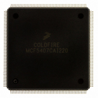
MCF5407CAI220 Freescale Semiconductor, MCF5407CAI220 Datasheet - Page 54

MCF5407CAI220
Manufacturer Part Number
MCF5407CAI220
Description
IC MPU 32B 220MHZ COLDF 208-FQFP
Manufacturer
Freescale Semiconductor
Series
MCF540xr
Specifications of MCF5407CAI220
Core Processor
Coldfire V4
Core Size
32-Bit
Speed
220MHz
Connectivity
EBI/EMI, I²C, UART/USART
Peripherals
DMA, WDT
Number Of I /o
16
Program Memory Type
ROMless
Ram Size
4K x 8
Voltage - Supply (vcc/vdd)
1.65 V ~ 3.6 V
Oscillator Type
External
Operating Temperature
-40°C ~ 85°C
Package / Case
208-FQFP
Processor Series
MCF540x
Core
ColdFire V4
Data Bus Width
32 bit
Program Memory Size
8 KB
Data Ram Size
4 KB
Maximum Clock Frequency
162 MHz
Number Of Programmable I/os
16
Operating Supply Voltage
1.8 V to 3.3 V
Mounting Style
SMD/SMT
3rd Party Development Tools
JLINK-CF-BDM26, EWCF
Cpu Speed
220MHz
Embedded Interface Type
I2C, UART
Digital Ic Case Style
FQFP
No. Of Pins
208
Supply Voltage Range
3.3V
Rohs Compliant
Yes
For Use With
M5407C3 - KIT EVAL FOR MCF5407 W/ETHERNET
Lead Free Status / RoHS Status
Lead free / RoHS Compliant
Eeprom Size
-
Program Memory Size
-
Data Converters
-
Lead Free Status / Rohs Status
Lead free / RoHS Compliant
Available stocks
Company
Part Number
Manufacturer
Quantity
Price
Company:
Part Number:
MCF5407CAI220
Manufacturer:
Freescale
Quantity:
789
Company:
Part Number:
MCF5407CAI220
Manufacturer:
Freescale Semiconductor
Quantity:
10 000
- Current page: 54 of 546
- Download datasheet (7Mb)
ColdFire Module Description
1.3.5 UART Modules
The MCF5407 contains two UARTs, which function independently. One UART has been
enhanced to provide synchronous operation and a CODEC interface for soft modem
support. Either UART can be clocked by the system bus clock, eliminating the need for an
external crystal. Each UART module interfaces directly to the CPU, as shown in Figure 1-2.
Each UART module consists of the following major functional areas:
UART1 is enhanced to provide a CODEC interface for soft modem support. UART1 can be
programmed to function like UART0 or in one of following modem modes:
Each UART contains an programmable clock-rate generator. Data formats can be 5, 6, 7,
or 8 bits with even, odd, or no parity, and up to 2 stop bits in 1/16 increments. The UARTs
include the following transmit and receive FIFO buffers:
The UART modules also provide several error-detection and maskable-interrupt
capabilities. Modem support includes request-to-send (RTS) and clear-to-send (CTS) lines.
CLKIN provides the time base through a programmable prescaler. The UART time scale
can also be sourced from a timer input. Full-duplex, auto-echo loopback, local loopback,
1-10
• Serial communication channel
• 16-bit divider for clock generation
• Internal channel control logic
• Interrupt control logic
• An 8-bit CODEC interface
• A 16-bit CODEC interface
• An audio CODEC ’97 (AC97) digital interface controller
• UART0 has a 4-byte FIFO receive buffer and a 2-byte FIFO transmit buffer.
• In UART1, the Tx and Rx FIFOs can hold the following:
— 32 1-byte samples when programmed as a UART or as an 8-bit CODEC interface
— 16 2-byte samples when programmed as a 16-bit CODEC interface
— 16 20-bit samples when programmed as a Digital AC ’97 Controller
System Integration
Module (SIM)
Controller
Interrupt
Figure 1-2. UART Module Block Diagram
Internal Channel
Interrupt Control
Control Logic
Logic
MCF5407 User’s Manual
UART
Communications
Programmable
Generation
Channel
Clock
Serial
CTS
RTS
RxD
TxD
CLKIN
or
External clock (TIN)
Related parts for MCF5407CAI220
Image
Part Number
Description
Manufacturer
Datasheet
Request
R
Part Number:
Description:
Mcf5407 Coldfire Integrated Microprocessor User
Manufacturer:
Freescale Semiconductor, Inc
Datasheet:
Part Number:
Description:
Manufacturer:
Freescale Semiconductor, Inc
Datasheet:
Part Number:
Description:
Manufacturer:
Freescale Semiconductor, Inc
Datasheet:
Part Number:
Description:
Manufacturer:
Freescale Semiconductor, Inc
Datasheet:
Part Number:
Description:
Manufacturer:
Freescale Semiconductor, Inc
Datasheet:
Part Number:
Description:
Manufacturer:
Freescale Semiconductor, Inc
Datasheet:
Part Number:
Description:
Manufacturer:
Freescale Semiconductor, Inc
Datasheet:
Part Number:
Description:
Manufacturer:
Freescale Semiconductor, Inc
Datasheet:
Part Number:
Description:
Manufacturer:
Freescale Semiconductor, Inc
Datasheet:
Part Number:
Description:
Manufacturer:
Freescale Semiconductor, Inc
Datasheet:
Part Number:
Description:
Manufacturer:
Freescale Semiconductor, Inc
Datasheet:
Part Number:
Description:
Manufacturer:
Freescale Semiconductor, Inc
Datasheet:
Part Number:
Description:
Manufacturer:
Freescale Semiconductor, Inc
Datasheet:
Part Number:
Description:
Manufacturer:
Freescale Semiconductor, Inc
Datasheet:
Part Number:
Description:
Manufacturer:
Freescale Semiconductor, Inc
Datasheet:


