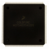
MCF5407CAI220 Freescale Semiconductor, MCF5407CAI220 Datasheet - Page 201

MCF5407CAI220
Manufacturer Part Number
MCF5407CAI220
Description
IC MPU 32B 220MHZ COLDF 208-FQFP
Manufacturer
Freescale Semiconductor
Series
MCF540xr
Specifications of MCF5407CAI220
Core Processor
Coldfire V4
Core Size
32-Bit
Speed
220MHz
Connectivity
EBI/EMI, I²C, UART/USART
Peripherals
DMA, WDT
Number Of I /o
16
Program Memory Type
ROMless
Ram Size
4K x 8
Voltage - Supply (vcc/vdd)
1.65 V ~ 3.6 V
Oscillator Type
External
Operating Temperature
-40°C ~ 85°C
Package / Case
208-FQFP
Processor Series
MCF540x
Core
ColdFire V4
Data Bus Width
32 bit
Program Memory Size
8 KB
Data Ram Size
4 KB
Maximum Clock Frequency
162 MHz
Number Of Programmable I/os
16
Operating Supply Voltage
1.8 V to 3.3 V
Mounting Style
SMD/SMT
3rd Party Development Tools
JLINK-CF-BDM26, EWCF
Cpu Speed
220MHz
Embedded Interface Type
I2C, UART
Digital Ic Case Style
FQFP
No. Of Pins
208
Supply Voltage Range
3.3V
Rohs Compliant
Yes
For Use With
M5407C3 - KIT EVAL FOR MCF5407 W/ETHERNET
Lead Free Status / RoHS Status
Lead free / RoHS Compliant
Eeprom Size
-
Program Memory Size
-
Data Converters
-
Lead Free Status / Rohs Status
Lead free / RoHS Compliant
Available stocks
Company
Part Number
Manufacturer
Quantity
Price
Company:
Part Number:
MCF5407CAI220
Manufacturer:
Freescale
Quantity:
789
Company:
Part Number:
MCF5407CAI220
Manufacturer:
Freescale Semiconductor
Quantity:
10 000
- Current page: 201 of 546
- Download datasheet (7Mb)
1
5.5.3.3.13 Write Debug Module Register (
The operand (longword) data is written to the specified debug module register. All 32 bits
of the register are altered by the write. DSCLK must be inactive while the debug module
register writes from the CPU accesses are performed using the WDEBUG instruction.
Command Format:
Table 5-6 shows the definition of the DRc write encoding.
Command Sequence:
Operand Data:
Result Data:
5.6 Real-Time Debug Support
The ColdFire Family provides support debugging real-time applications. For these types of
embedded systems, the processor must continue to operate during debug. The foundation
of this area of debug support is that while the processor cannot be halted to allow
debugging, the system can generally tolerate small intrusions into the real-time operation.
The debug module provides three types of breakpoints—PC with mask, operand address
range, and data with mask. These breakpoints can be configured into one- or two-level
triggers with the exact trigger response also programmable. The debug module
programming model can be written from either the external development system using the
debug serial interface or from the processor’s supervisor programming model using the
WDEBUG instruction. Only CSR is readable using the external development system.
15
Note: 0x4 is a three-bit field
0x2
12
WDMREG
Figure 5-44.
???
Figure 5-45.
Longword data is written into the specified debug register. The data
is supplied most-significant word first.
Command complete status (0xFFFF) is returned when register write
is complete.
11
0xC
Chapter 5. Debug Support
WDMREG
"NOT READY"
"ILLEGAL"
MS DATA
WDMREG
XXX
D[31:16]
8
D[15:0]
BDM Command Format
Command Sequence
7
"NOT READY"
"NOT READY"
NEXT CMD
LS DATA
WDMREG
0x4
1
5
)
"CMD COMPLETE"
NEXT CMD
4
Real-Time Debug Support
DRc
5-45
0
Related parts for MCF5407CAI220
Image
Part Number
Description
Manufacturer
Datasheet
Request
R
Part Number:
Description:
Mcf5407 Coldfire Integrated Microprocessor User
Manufacturer:
Freescale Semiconductor, Inc
Datasheet:
Part Number:
Description:
Manufacturer:
Freescale Semiconductor, Inc
Datasheet:
Part Number:
Description:
Manufacturer:
Freescale Semiconductor, Inc
Datasheet:
Part Number:
Description:
Manufacturer:
Freescale Semiconductor, Inc
Datasheet:
Part Number:
Description:
Manufacturer:
Freescale Semiconductor, Inc
Datasheet:
Part Number:
Description:
Manufacturer:
Freescale Semiconductor, Inc
Datasheet:
Part Number:
Description:
Manufacturer:
Freescale Semiconductor, Inc
Datasheet:
Part Number:
Description:
Manufacturer:
Freescale Semiconductor, Inc
Datasheet:
Part Number:
Description:
Manufacturer:
Freescale Semiconductor, Inc
Datasheet:
Part Number:
Description:
Manufacturer:
Freescale Semiconductor, Inc
Datasheet:
Part Number:
Description:
Manufacturer:
Freescale Semiconductor, Inc
Datasheet:
Part Number:
Description:
Manufacturer:
Freescale Semiconductor, Inc
Datasheet:
Part Number:
Description:
Manufacturer:
Freescale Semiconductor, Inc
Datasheet:
Part Number:
Description:
Manufacturer:
Freescale Semiconductor, Inc
Datasheet:
Part Number:
Description:
Manufacturer:
Freescale Semiconductor, Inc
Datasheet:


