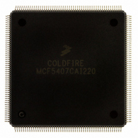
MCF5407CAI220 Freescale Semiconductor, MCF5407CAI220 Datasheet - Page 226

MCF5407CAI220
Manufacturer Part Number
MCF5407CAI220
Description
IC MPU 32B 220MHZ COLDF 208-FQFP
Manufacturer
Freescale Semiconductor
Series
MCF540xr
Specifications of MCF5407CAI220
Core Processor
Coldfire V4
Core Size
32-Bit
Speed
220MHz
Connectivity
EBI/EMI, I²C, UART/USART
Peripherals
DMA, WDT
Number Of I /o
16
Program Memory Type
ROMless
Ram Size
4K x 8
Voltage - Supply (vcc/vdd)
1.65 V ~ 3.6 V
Oscillator Type
External
Operating Temperature
-40°C ~ 85°C
Package / Case
208-FQFP
Processor Series
MCF540x
Core
ColdFire V4
Data Bus Width
32 bit
Program Memory Size
8 KB
Data Ram Size
4 KB
Maximum Clock Frequency
162 MHz
Number Of Programmable I/os
16
Operating Supply Voltage
1.8 V to 3.3 V
Mounting Style
SMD/SMT
3rd Party Development Tools
JLINK-CF-BDM26, EWCF
Cpu Speed
220MHz
Embedded Interface Type
I2C, UART
Digital Ic Case Style
FQFP
No. Of Pins
208
Supply Voltage Range
3.3V
Rohs Compliant
Yes
For Use With
M5407C3 - KIT EVAL FOR MCF5407 W/ETHERNET
Lead Free Status / RoHS Status
Lead free / RoHS Compliant
Eeprom Size
-
Program Memory Size
-
Data Converters
-
Lead Free Status / Rohs Status
Lead free / RoHS Compliant
Available stocks
Company
Part Number
Manufacturer
Quantity
Price
Company:
Part Number:
MCF5407CAI220
Manufacturer:
Freescale
Quantity:
789
Company:
Part Number:
MCF5407CAI220
Manufacturer:
Freescale Semiconductor
Quantity:
10 000
- Current page: 226 of 546
- Download datasheet (7Mb)
Programming Model
6.2.10.1.1 Arbitration for Internally Generated Transfers (MPARK[PARK])
MPARK[PARK] prioritizes internal transfers, which can be initiated by the core and the
on-chip DMA module, which contains all four DMA channels. Priority among the four
DMA channels in the module is determined by the BWC bits in their respective DMA
control registers (see Chapter 12, “DMA Controller Module”).
The four arbitration schemes for internally generated transfers are described as follows:
6-12
Bits
2–0
3
• Round-robin scheme (PARK = 00)—Figure 6-10 shows round-robin arbitration
between the core and DMA module. Bus mastership alternates between the core and
DMA module.
The DMA module presents only the highest-priority DMA request, and bus
mastership alternates between the core and DMA channel as long as both are
requesting bus mastership. Section 12.5.4.1, “External Request and Acknowledge
Operation,” includes a timing diagram showing a lower-priority DMA transfer.
When the processor is initialized, the core has first priority. If DMA channels 0 and
1 (both set to BWC = 010) assert an internal bus request during a core-generated bus
transfer, DMA channel 0 would gain bus mastership next. However, if the core
requests the bus during this DMA transfer, bus mastership returns to the core rather
than being granted to DMA channel 1.
Note that the internal DMA has higher priority than the core if the internal DMA has
its bandwidth BWC bits set to 000 (maximum bandwidth).
SHOWDATA Enable internal register data bus to be driven on external bus. EARBCTRL must be set for
Name
—
Table 6-6. MPARK Field Descriptions (Continued)
Figure 6-10. Round Robin Arbitration (PARK = 00)
this function to work. Section 6.2.10.1.2, “Arbitration between Internal and External Masters
for Accessing Internal Resources,” describes the proper use of SHOWDATA.
0 Do not drive internal register data bus values to external bus.
1 Drive internal register data bus values to external bus.
Reserved, should be cleared.
(Alternates between Core and DMA Module)
CORE
Internal Bus Mastership
3rd
5th
1st
MCF5407 User’s Manual
4th
2nd
Description
DMA MODULE
Channel 0
Channel 1
Channel 2
Channel 3
Related parts for MCF5407CAI220
Image
Part Number
Description
Manufacturer
Datasheet
Request
R
Part Number:
Description:
Mcf5407 Coldfire Integrated Microprocessor User
Manufacturer:
Freescale Semiconductor, Inc
Datasheet:
Part Number:
Description:
Manufacturer:
Freescale Semiconductor, Inc
Datasheet:
Part Number:
Description:
Manufacturer:
Freescale Semiconductor, Inc
Datasheet:
Part Number:
Description:
Manufacturer:
Freescale Semiconductor, Inc
Datasheet:
Part Number:
Description:
Manufacturer:
Freescale Semiconductor, Inc
Datasheet:
Part Number:
Description:
Manufacturer:
Freescale Semiconductor, Inc
Datasheet:
Part Number:
Description:
Manufacturer:
Freescale Semiconductor, Inc
Datasheet:
Part Number:
Description:
Manufacturer:
Freescale Semiconductor, Inc
Datasheet:
Part Number:
Description:
Manufacturer:
Freescale Semiconductor, Inc
Datasheet:
Part Number:
Description:
Manufacturer:
Freescale Semiconductor, Inc
Datasheet:
Part Number:
Description:
Manufacturer:
Freescale Semiconductor, Inc
Datasheet:
Part Number:
Description:
Manufacturer:
Freescale Semiconductor, Inc
Datasheet:
Part Number:
Description:
Manufacturer:
Freescale Semiconductor, Inc
Datasheet:
Part Number:
Description:
Manufacturer:
Freescale Semiconductor, Inc
Datasheet:
Part Number:
Description:
Manufacturer:
Freescale Semiconductor, Inc
Datasheet:


