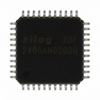
Z8F2480AN020SG Zilog, Z8F2480AN020SG Datasheet - Page 164

Z8F2480AN020SG
Manufacturer Part Number
Z8F2480AN020SG
Description
MCU 8BIT 24KB FLASH 44LQFP
Manufacturer
Zilog
Series
Encore!® XP®r
Specifications of Z8F2480AN020SG
Core Processor
Z8
Core Size
8-Bit
Speed
20MHz
Connectivity
I²C, IrDA, LIN, SPI, UART/USART
Peripherals
Brown-out Detect/Reset, LED, LVD, POR, PWM, Temp Sensor, WDT
Number Of I /o
37
Program Memory Size
24KB (24K x 8)
Program Memory Type
FLASH
Ram Size
3K x 8
Voltage - Supply (vcc/vdd)
1.8 V ~ 3.6 V
Data Converters
A/D 8x10b
Oscillator Type
Internal
Operating Temperature
0°C ~ 70°C
Package / Case
44-LQFP
Processor Series
Z8F248x
Core
eZ8
Data Bus Width
8 bit
Data Ram Size
2 KB
Interface Type
I2C, SPI, UART
Maximum Clock Frequency
20 MHz
Number Of Programmable I/os
37
Number Of Timers
3
Maximum Operating Temperature
+ 70 C
Mounting Style
SMD/SMT
Minimum Operating Temperature
0 C
On-chip Adc
10 bit, 8 Channel
For Use With
770-1002 - ISP 4PORT ZILOG Z8 ENCORE! MCU269-4643 - KIT DEV Z8 ENCORE XP 28-PIN269-4630 - DEV KIT FOR Z8 ENCORE 8K/4K269-4629 - KIT DEV Z8 ENCORE XP 28-PIN269-4628 - KIT DEV Z8 ENCORE XP 8-PIN
Lead Free Status / RoHS Status
Lead free / RoHS Compliant
Eeprom Size
-
Lead Free Status / Rohs Status
Details
Other names
269-4676
Available stocks
Company
Part Number
Manufacturer
Quantity
Price
Company:
Part Number:
Z8F2480AN020SG
Manufacturer:
Zilog
Quantity:
85
- Current page: 164 of 399
- Download datasheet (19Mb)
PS025011-1010
LIN Protocol Mode
The Local Interconnect Network (LIN) protocol as supported by the LIN-UART module is
defined in rev 2.0 of the LIN Specification Package. The LIN protocol specification
covers all aspects of transferring information between LIN Master and Slave devices using
message frames including error detection and recovery, SLEEP mode and wake up from
SLEEP mode. The LIN-UART hardware in LIN mode provides character transfers to
support the LIN protocol including Break transmission and detection, Wake-up
transmission and detection, and Slave autobauding. Part of the error detection of the LIN
protocol is for both master and slave devices to monitor their receive data when
transmitting. If the receive and transmit data streams do not match, the LIN-UART asserts
the
of the protocol depends on software requiring the use of an additional general purpose
timer. The LIN mode of the LIN-UART does not provide any hardware support for
computing/verifying the checksum field or verifying the contents of the identifier field.
These fields are treated as data and are not interpreted by hardware. The checksum
calculation/verification can easily be implemented in software via the ADC (Add with
Carry) instruction.
The LIN bus contains a single Master and one or more Slaves. The LIN master is
responsible for transmitting the message frame header which consists of the Break,
Synch and Identifier fields. Either the master or one of the slaves transmits the associated
response section of the message which consists of data characters followed by a checksum
character.
In LIN mode, the interrupts defined for normal UART operation still apply with the
following changes:
•
•
•
•
PLE
Parity Error (
The
is transmitting. This applies to both Master and Slave operating modes.
The Break Detect interrupt (
detected by the slave (break condition for at least 11 bit times). Software can use this
interrupt to start a timer checking for message frame timeout. The duration of the break
can be read in the
The Break Detect interrupt (
Wake-up message has been received, if the LIN-UART is in Lin Sleep state.
In LIN SLAVE mode, if the BRG counter overflows while measuring the autobaud period
(Start bit to beginning of bit 7 of autobaud character) an Overrun Error is indicated (
in the Status0 register). In this case, software sets the LinState field back to
slave ignores the current message and waits for the next break. The Baud Reload High and
Low registers are not updated by hardware if this autobaud error occurs. The
set if a data overrun error occurs.
bit (physical layer error bit in Status0 register). The message frame timeout aspect
PLE
bit indicates that receive data does not match transmit data when the LIN-UART
PE
bit in Status0 register) is redefined as the Physical Layer Error (
RxBreakLength[3:0]
P R E L I M I N A R Y
BRKD
BRKD
bit in Status0 register) indicates when a Break is
bit in Status0 register) indicates when a
field of the Mode Select and Status register.
Z8 Encore! XP
Product Specification
®
F1680 Series
10b
OE
, where the
bit is also
LIN-UART
PLE
OE
) bit.
bit
150
Related parts for Z8F2480AN020SG
Image
Part Number
Description
Manufacturer
Datasheet
Request
R

Part Number:
Description:
Communication Controllers, ZILOG INTELLIGENT PERIPHERAL CONTROLLER (ZIP)
Manufacturer:
Zilog, Inc.
Datasheet:

Part Number:
Description:
KIT DEV FOR Z8 ENCORE 16K TO 64K
Manufacturer:
Zilog
Datasheet:

Part Number:
Description:
KIT DEV Z8 ENCORE XP 28-PIN
Manufacturer:
Zilog
Datasheet:

Part Number:
Description:
DEV KIT FOR Z8 ENCORE 8K/4K
Manufacturer:
Zilog
Datasheet:

Part Number:
Description:
KIT DEV Z8 ENCORE XP 28-PIN
Manufacturer:
Zilog
Datasheet:

Part Number:
Description:
DEV KIT FOR Z8 ENCORE 4K TO 8K
Manufacturer:
Zilog
Datasheet:

Part Number:
Description:
CMOS Z8 microcontroller. ROM 16 Kbytes, RAM 256 bytes, speed 16 MHz, 32 lines I/O, 3.0V to 5.5V
Manufacturer:
Zilog, Inc.
Datasheet:

Part Number:
Description:
Low-cost microcontroller. 512 bytes ROM, 61 bytes RAM, 8 MHz
Manufacturer:
Zilog, Inc.
Datasheet:

Part Number:
Description:
Z8 4K OTP Microcontroller
Manufacturer:
Zilog, Inc.
Datasheet:

Part Number:
Description:
CMOS SUPER8 ROMLESS MCU
Manufacturer:
Zilog, Inc.
Datasheet:

Part Number:
Description:
SL1866 CMOSZ8 OTP Microcontroller
Manufacturer:
Zilog, Inc.
Datasheet:

Part Number:
Description:
SL1866 CMOSZ8 OTP Microcontroller
Manufacturer:
Zilog, Inc.
Datasheet:

Part Number:
Description:
OTP (KB) = 1, RAM = 125, Speed = 12, I/O = 14, 8-bit Timers = 2, Comm Interfaces Other Features = Por, LV Protect, Voltage = 4.5-5.5V
Manufacturer:
Zilog, Inc.
Datasheet:

Part Number:
Description:
Manufacturer:
Zilog, Inc.
Datasheet:


