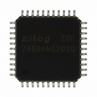
Z8F2480AN020SG Zilog, Z8F2480AN020SG Datasheet - Page 163

Z8F2480AN020SG
Manufacturer Part Number
Z8F2480AN020SG
Description
MCU 8BIT 24KB FLASH 44LQFP
Manufacturer
Zilog
Series
Encore!® XP®r
Specifications of Z8F2480AN020SG
Core Processor
Z8
Core Size
8-Bit
Speed
20MHz
Connectivity
I²C, IrDA, LIN, SPI, UART/USART
Peripherals
Brown-out Detect/Reset, LED, LVD, POR, PWM, Temp Sensor, WDT
Number Of I /o
37
Program Memory Size
24KB (24K x 8)
Program Memory Type
FLASH
Ram Size
3K x 8
Voltage - Supply (vcc/vdd)
1.8 V ~ 3.6 V
Data Converters
A/D 8x10b
Oscillator Type
Internal
Operating Temperature
0°C ~ 70°C
Package / Case
44-LQFP
Processor Series
Z8F248x
Core
eZ8
Data Bus Width
8 bit
Data Ram Size
2 KB
Interface Type
I2C, SPI, UART
Maximum Clock Frequency
20 MHz
Number Of Programmable I/os
37
Number Of Timers
3
Maximum Operating Temperature
+ 70 C
Mounting Style
SMD/SMT
Minimum Operating Temperature
0 C
On-chip Adc
10 bit, 8 Channel
For Use With
770-1002 - ISP 4PORT ZILOG Z8 ENCORE! MCU269-4643 - KIT DEV Z8 ENCORE XP 28-PIN269-4630 - DEV KIT FOR Z8 ENCORE 8K/4K269-4629 - KIT DEV Z8 ENCORE XP 28-PIN269-4628 - KIT DEV Z8 ENCORE XP 8-PIN
Lead Free Status / RoHS Status
Lead free / RoHS Compliant
Eeprom Size
-
Lead Free Status / Rohs Status
Details
Other names
269-4676
Available stocks
Company
Part Number
Manufacturer
Quantity
Price
Company:
Part Number:
Z8F2480AN020SG
Manufacturer:
Zilog
Quantity:
85
- Current page: 163 of 399
- Download datasheet (19Mb)
PS025011-1010
MULTIPROCESSOR Mode Receive Interrupts
When MULTIPROCESSOR (9-bit) mode is enabled, the LIN-UART processes only
frames addressed to it. To determine whether a frame of data is addressed to the
LIN-UART can be made in hardware, software or a combination of the two, depending on
the multiprocessor configuration bits. In general, the address compare feature reduces
the load on the CPU, because it does not need to access the LIN-UART when it
receives data directed to other devices on the multinode network. The following three
MULTIPROCESSOR modes are available in hardware:
1. Interrupt on all address bytes.
2. Interrupt on matched address bytes and correctly framed data bytes.
3. Interrupt only on correctly framed data bytes.
These modes are selected with
For all MULTIPROCESSOR modes, bit MPEN of the LIN-UART Control 1 Register
must be set to 1.
The first scheme is enabled by writing
address bytes cause an interrupt, while data bytes never cause an interrupt. The interrupt
service routine checks the address byte which triggered the interrupt. If it matches the
LIN-UART address, the software clears MPMD[0]. At this point, each new incoming byte
interrupts the CPU. The software determines the end of the frame and checks for it by
reading the MPRX bit of the LIN-UART Status 1 Register for each incoming byte. If
MPRX=1, a new frame begins. If the address of this new frame is different from the
LIN-UART’s address, then MPMD[0] must be set to 1 by software, causing the
LIN-UART interrupts to go inactive until the next address byte. If the new frame’s address
matches the LIN-UART’s, then the data in the new frame is also processed.
The second scheme is enabled by setting MPMD[1:0] to 10B and writing the
LIN-UART’s address into the LIN-UART Address Compare Register. This mode
introduces more hardware control, interrupting only on frames that match the
LIN-UART’s address. When an incoming address byte does not match the LIN-UART’s
address, it is ignored. All successive data bytes in this frame are also ignored. When a
matching address byte occurs, an interrupt is issued and further interrupts occur on each
successive data byte. The first data byte in the frame has
Status 1 Register. When the next address byte occurs, the hardware compares it to the
LIN-UART’s address. If there is a match, the interrupt occurs and the NEWFRM bit is set to
the first byte of the new frame. If there is no match, the LIN-UART ignores all incoming
bytes until the next address match.
The third scheme is enabled by setting
address into the LIN-UART Address Compare Register. This mode is identical to the
second scheme, except that there are no interrupts on address bytes. The first data byte of
each frame remains accompanied by a
P R E L I M I N A R Y
MPMD[1:0]
MPMD
NEWFRM
01b
to MPMD[1:0]. In this mode, all incoming
in the LIN-UART Control 1 Register.
[1:0] to
assertion.
11B
Z8 Encore! XP
NEWFRM=1
and by writing the LIN-UART’s
Product Specification
in the LIN-UART
®
F1680 Series
LIN-UART
149
Related parts for Z8F2480AN020SG
Image
Part Number
Description
Manufacturer
Datasheet
Request
R

Part Number:
Description:
Communication Controllers, ZILOG INTELLIGENT PERIPHERAL CONTROLLER (ZIP)
Manufacturer:
Zilog, Inc.
Datasheet:

Part Number:
Description:
KIT DEV FOR Z8 ENCORE 16K TO 64K
Manufacturer:
Zilog
Datasheet:

Part Number:
Description:
KIT DEV Z8 ENCORE XP 28-PIN
Manufacturer:
Zilog
Datasheet:

Part Number:
Description:
DEV KIT FOR Z8 ENCORE 8K/4K
Manufacturer:
Zilog
Datasheet:

Part Number:
Description:
KIT DEV Z8 ENCORE XP 28-PIN
Manufacturer:
Zilog
Datasheet:

Part Number:
Description:
DEV KIT FOR Z8 ENCORE 4K TO 8K
Manufacturer:
Zilog
Datasheet:

Part Number:
Description:
CMOS Z8 microcontroller. ROM 16 Kbytes, RAM 256 bytes, speed 16 MHz, 32 lines I/O, 3.0V to 5.5V
Manufacturer:
Zilog, Inc.
Datasheet:

Part Number:
Description:
Low-cost microcontroller. 512 bytes ROM, 61 bytes RAM, 8 MHz
Manufacturer:
Zilog, Inc.
Datasheet:

Part Number:
Description:
Z8 4K OTP Microcontroller
Manufacturer:
Zilog, Inc.
Datasheet:

Part Number:
Description:
CMOS SUPER8 ROMLESS MCU
Manufacturer:
Zilog, Inc.
Datasheet:

Part Number:
Description:
SL1866 CMOSZ8 OTP Microcontroller
Manufacturer:
Zilog, Inc.
Datasheet:

Part Number:
Description:
SL1866 CMOSZ8 OTP Microcontroller
Manufacturer:
Zilog, Inc.
Datasheet:

Part Number:
Description:
OTP (KB) = 1, RAM = 125, Speed = 12, I/O = 14, 8-bit Timers = 2, Comm Interfaces Other Features = Por, LV Protect, Voltage = 4.5-5.5V
Manufacturer:
Zilog, Inc.
Datasheet:

Part Number:
Description:
Manufacturer:
Zilog, Inc.
Datasheet:


