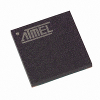
T89C51CC01CA-7CTIM Atmel, T89C51CC01CA-7CTIM Datasheet - Page 40

T89C51CC01CA-7CTIM
Manufacturer Part Number
T89C51CC01CA-7CTIM
Description
IC 8051 MCU FLASH 32K 64BGA
Manufacturer
Atmel
Series
AT89C CANr
Datasheets
1.T89C51CC01CA-7CTIM.pdf
(167 pages)
2.T89C51CC01CA-7CTIM.pdf
(12 pages)
3.T89C51CC01CA-7CTIM.pdf
(32 pages)
4.T89C51CC01CA-7CTIM.pdf
(29 pages)
Specifications of T89C51CC01CA-7CTIM
Core Processor
8051
Core Size
8-Bit
Speed
40MHz
Connectivity
CAN, UART/USART
Peripherals
POR, PWM, WDT
Number Of I /o
34
Program Memory Size
32KB (32K x 8)
Program Memory Type
FLASH
Eeprom Size
2K x 8
Ram Size
1.25K x 8
Voltage - Supply (vcc/vdd)
3 V ~ 5.5 V
Data Converters
A/D 8x10b
Oscillator Type
External
Operating Temperature
-40°C ~ 85°C
Package / Case
64-BGA
For Use With
AT89STK-06 - KIT DEMOBOARD 8051 MCU W/CAN
Lead Free Status / RoHS Status
Contains lead / RoHS non-compliant
Other names
T89C51CC01CA7CTIM
Available stocks
Company
Part Number
Manufacturer
Quantity
Price
- T89C51CC01CA-7CTIM PDF datasheet
- T89C51CC01CA-7CTIM PDF datasheet #2
- T89C51CC01CA-7CTIM PDF datasheet #3
- T89C51CC01CA-7CTIM PDF datasheet #4
- Current page: 40 of 167
- Download datasheet (2Mb)
Hardware Security Byte
40
A/T89C51CC01
Figure 22. Flash and Extra Row Programming Procedure
The following procedure is used to program the Hardware
and is summarized in Figure 23:
•
•
•
•
•
•
•
Set FPS and map Hardware byte (FCON = 0x0C)
Save and disable the interrupts.
Load DPTR at address 0000h.
Load Accumulator register with the data to load.
Execute the MOVX @DPTR, A instruction.
Launch the programming by writing the data sequence 54h followed by A4h in
FCON register. This step of the procedure must be executed from FM1. The end of
the programming indicated by the FBUSY flag cleared.
The end of the programming indicated by the FBusy flag cleared.
Restore the interrupts.
Column Latches Loading
Launch Programming
Save and Disable IT
End Programming
Programming
Flash Spaces
see Figure 21
FCON = Axh
FCON = 5xh
FCON = 00h
Clear Mode
Cleared?
Restore IT
FBusy
EA = 0
Security
4129N–CAN–03/08
Byte space
Related parts for T89C51CC01CA-7CTIM
Image
Part Number
Description
Manufacturer
Datasheet
Request
R

Part Number:
Description:
Enhanced 8-Bit Microcontroller
Manufacturer:
Atmel
Datasheet:

Part Number:
Description:
DEV KIT FOR AVR/AVR32
Manufacturer:
Atmel
Datasheet:

Part Number:
Description:
INTERVAL AND WIPE/WASH WIPER CONTROL IC WITH DELAY
Manufacturer:
ATMEL Corporation
Datasheet:

Part Number:
Description:
Low-Voltage Voice-Switched IC for Hands-Free Operation
Manufacturer:
ATMEL Corporation
Datasheet:

Part Number:
Description:
MONOLITHIC INTEGRATED FEATUREPHONE CIRCUIT
Manufacturer:
ATMEL Corporation
Datasheet:

Part Number:
Description:
AM-FM Receiver IC U4255BM-M
Manufacturer:
ATMEL Corporation
Datasheet:

Part Number:
Description:
Monolithic Integrated Feature Phone Circuit
Manufacturer:
ATMEL Corporation
Datasheet:

Part Number:
Description:
Multistandard Video-IF and Quasi Parallel Sound Processing
Manufacturer:
ATMEL Corporation
Datasheet:

Part Number:
Description:
High-performance EE PLD
Manufacturer:
ATMEL Corporation
Datasheet:

Part Number:
Description:
8-bit Flash Microcontroller
Manufacturer:
ATMEL Corporation
Datasheet:

Part Number:
Description:
2-Wire Serial EEPROM
Manufacturer:
ATMEL Corporation
Datasheet:


